32-bit hat, with LEDs
Built in November 2015 (now-traditional multi-year writeup delay applied)
Is this thing on..? It’s been a while since I’ve written one of these.
So, the hat. It’s been on the writeup pile for almost 6 years, nagging away. Finally it’s its time to shine! NO PUN ESCAPES
Anyway, the hat. It seemed like a good idea, and I even wore it out dancing. I know, so cool.
This hat had been through at least two fancy-dress events, and had a natty band aftermarket mod even before the LEDs.
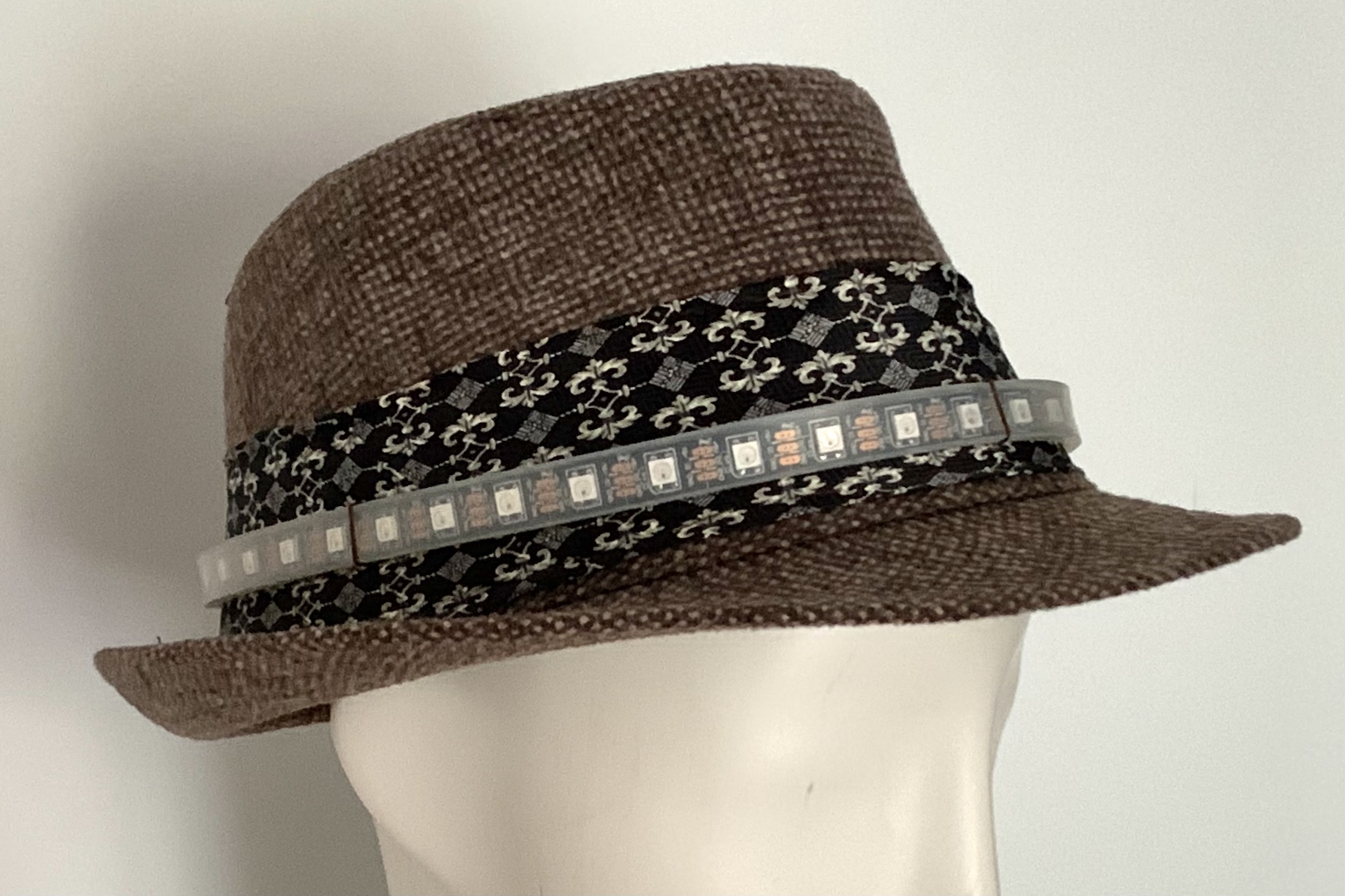
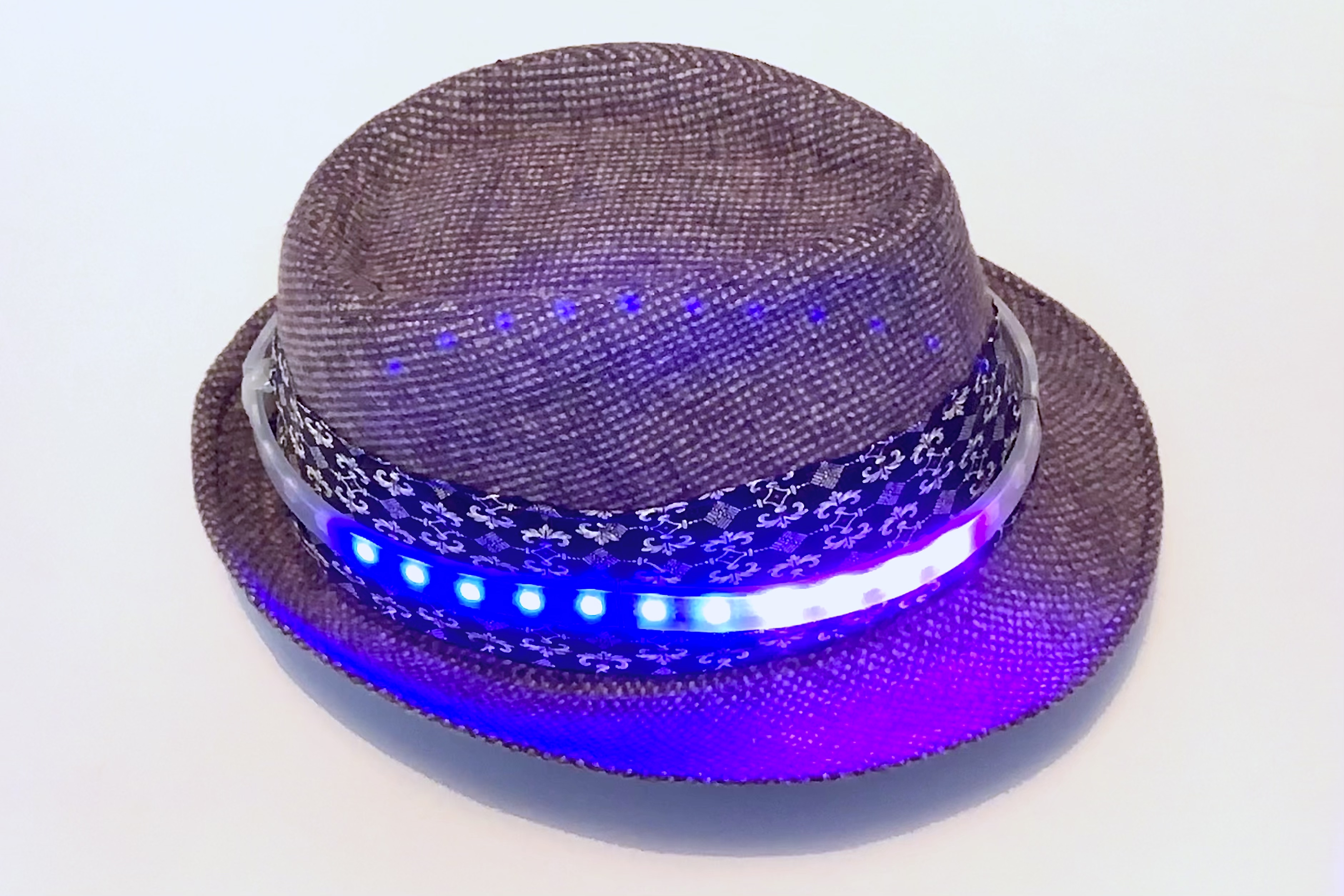
Long story short, got a hat, put a battery, ARM Cortex-M0 microcontroller, accelerometer in it and a strip of full-colour RGB LEDs around it. The LEDs then react to movement, with an effect similar to a spirit level: as it tilts, a spark travels to the highest point. The spark rolls around, fading out nicely.
Hardware
Pretty much full bodge-city, and made in a real rush before a party.
Parts:
- Charity shop Trilby (someone’s going to correct me that this is not an ISO standard Trilby and is in fact a Westcountry Colonel Chap Trilby, or something). Bugger it – a hat.
- A WS2812B strip of 38 LEDs. 38 is what would fit around the hat.
- Cheapo ADXL345 board.
- Cheapo STM32F030 board (I <3 these boards! So power, such price wow).
- Cheapo Li-Ion charging board and 5V step-up module all-in-one (AKA “powerbank board”).
- Li-Ion flat/pouch-style battery.
- Obviously some hot glue in there somewhere too.
No schematic, sorry, it was quite freeform. The battery is attached to charging board. That connects to the rest of the system via a 0.1” header/disconnectable “power switch” cable. The 5V power then directly feeds the LED strip, from Cortex-M0 board (which then generates 3.3V itself).
The ADXL345 accelerometer is joined directly to the the STM32 board at what was the UART header, which is configured for I2C:
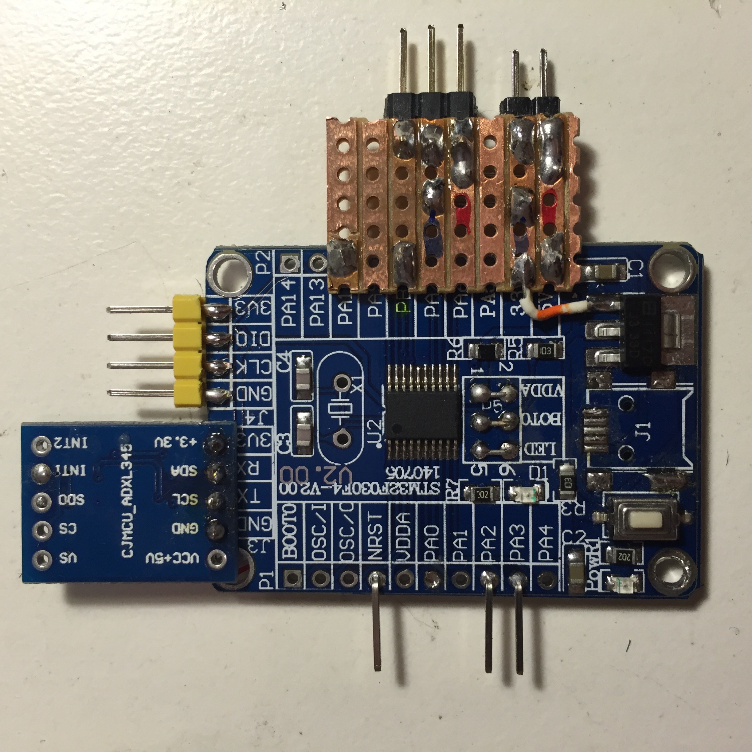
The STM32 board is also stripped of any unnecessary or especially pointy parts, such as jumpers/pin headers, to make it as flat and pain-free as possible.
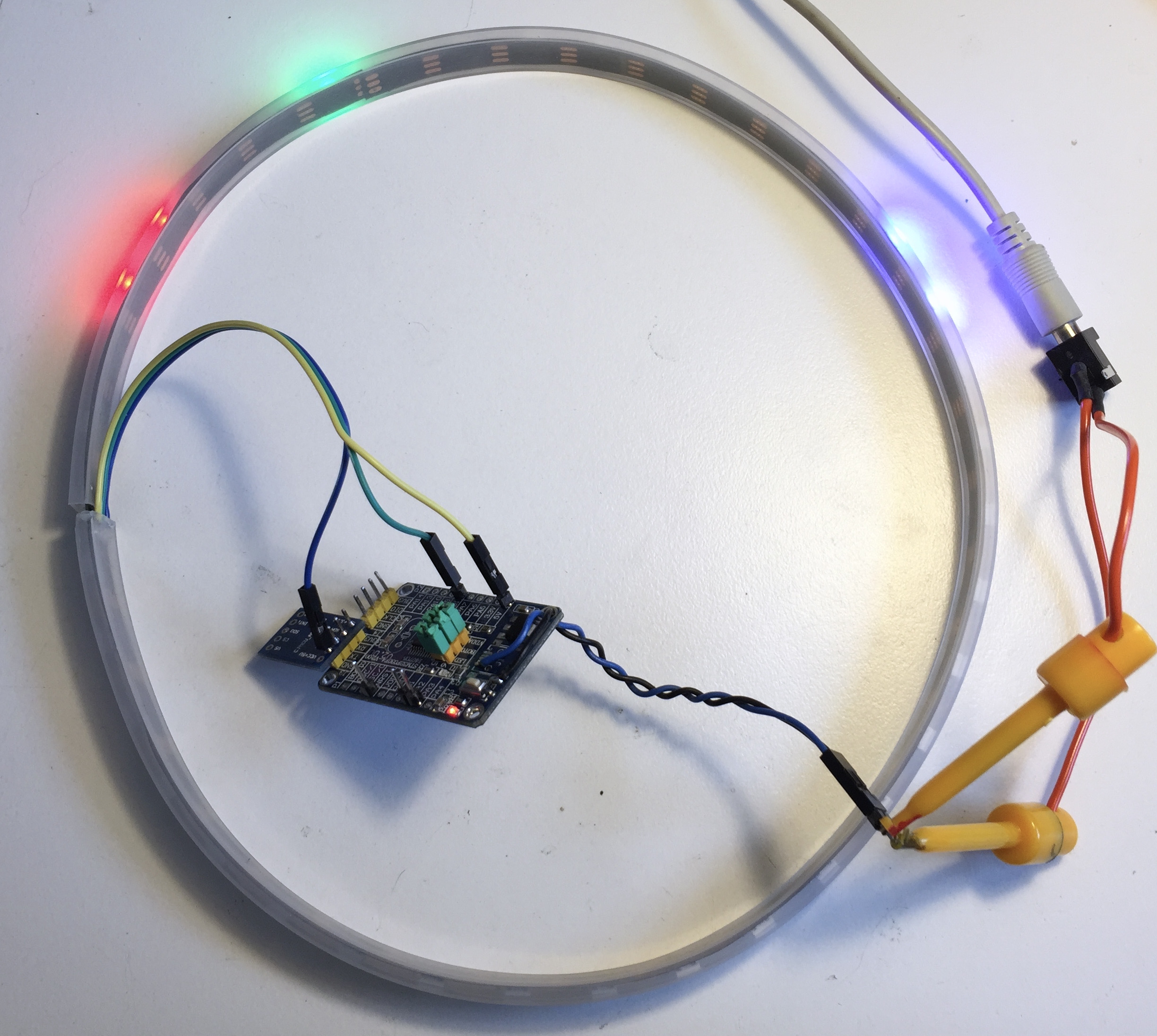
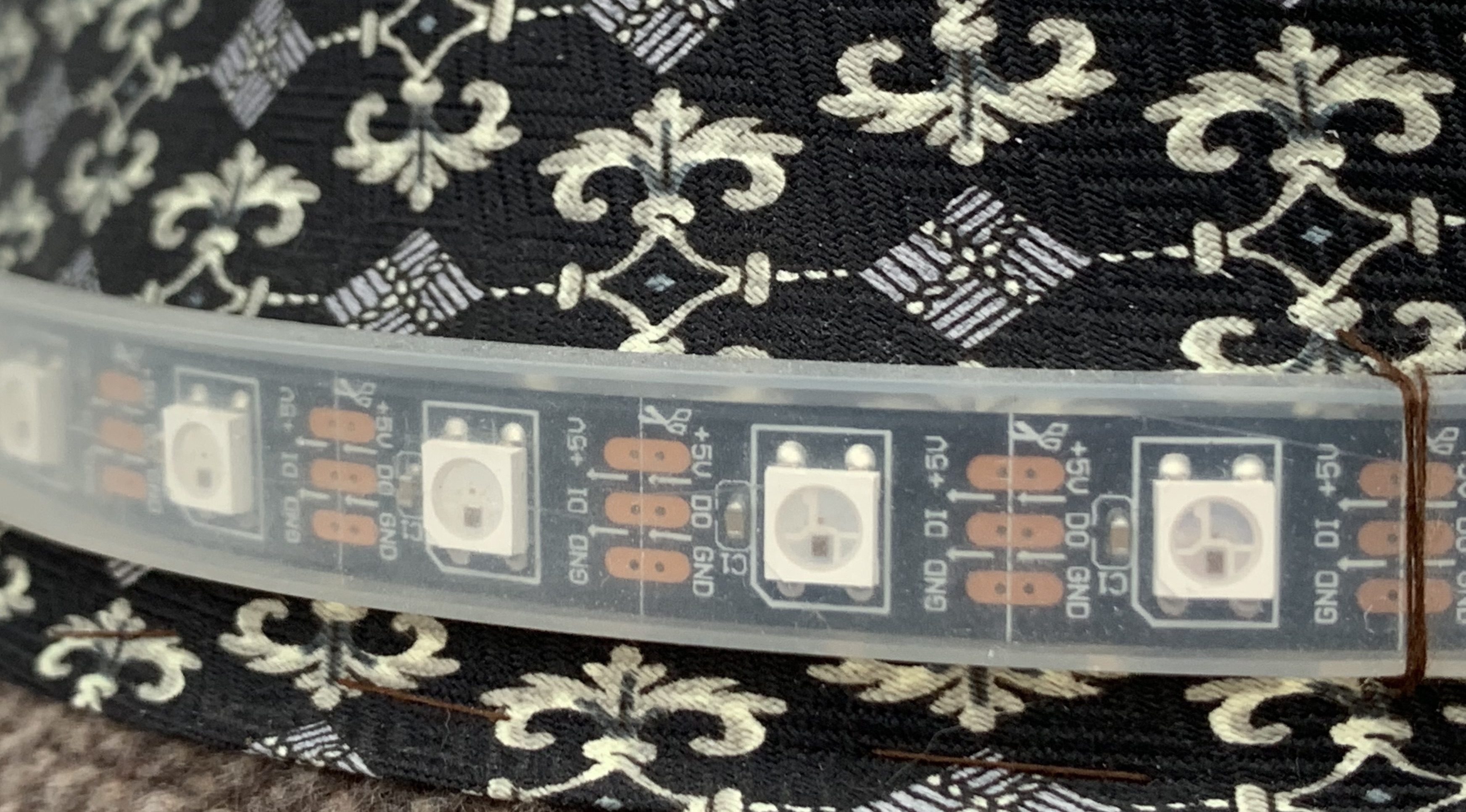
The LED strip is bent into a ring and soldered back onto itself. 5V and ground are linked at the join, whereas DI enters at the join and DO is left hanging. This is done for mechanical stability, and can’t hurt for power distribution too. Here’s the ring in testing:
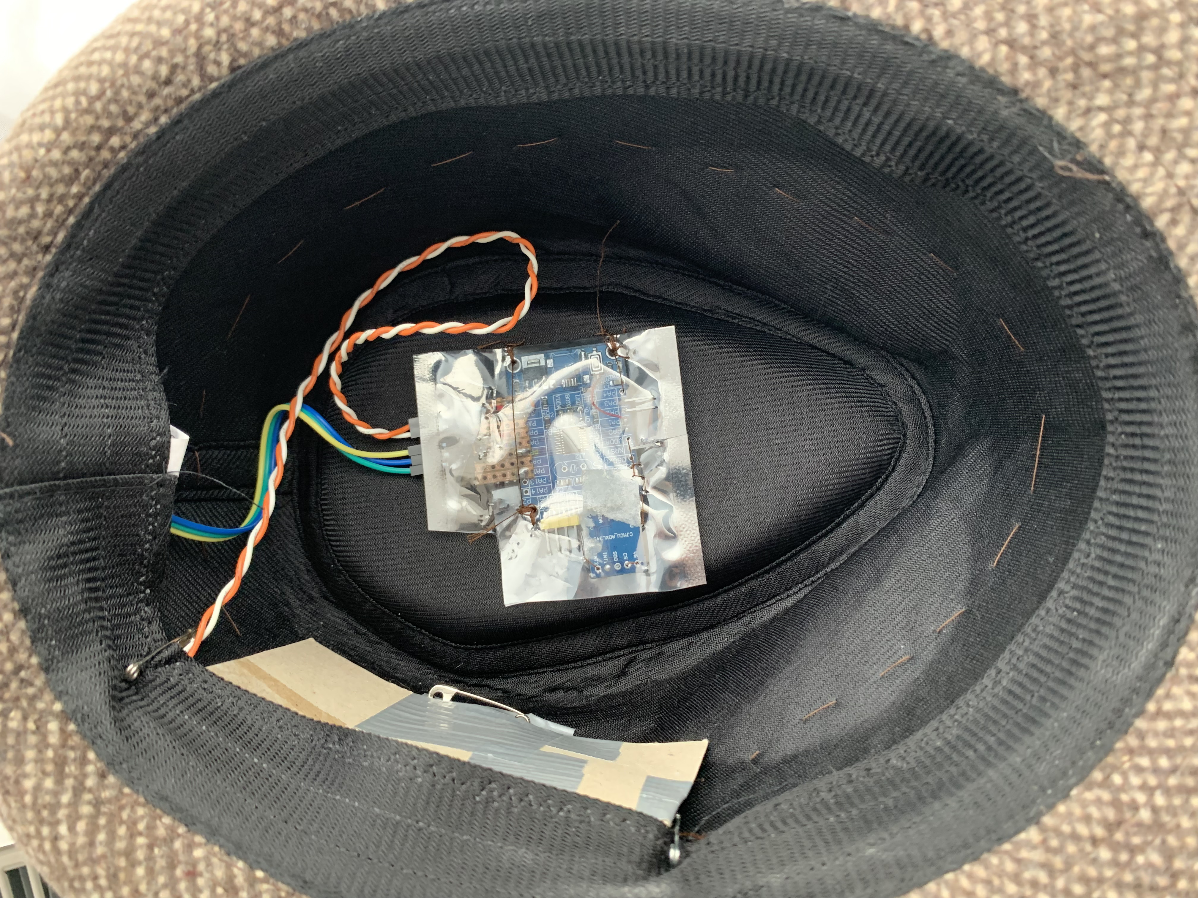
The electronics are mounted in an antistatic bag (with a hole for the power “switch” header pins, wires, etc.), and the bag sewn into the top of the hat:
The LED ring is attached via a small hole, and sewn on with periodic thread loops:
Software
The firmware goes through an initial “which way is up?” calibration phase for the first few seconds, where it:
- Lights a simple red dotted pattern to warn the user it’s about to sample which way is up, so put it on quick and stand as naturally as you can with such exciting technology on your head,
- Lights a simple white dotted pattern, as it measures the “resting vector”, i.e. which way is up.
This “resting vector” is thereafter used as the reference for determining whether the hat is tilted, and in which direction.
Tilt direction vectors
The main loop’s job is to regulate the rate of LED updates, read the accelerometer, calculate a position to draw a bright spark “blob”, and update the LEDs.
The accelerometer returns a 3D vector of a force; when not being externally accelerated, the vector represents the direction of Earth’s gravity, i.e. ‘down’.
Trigonometry is both fun and useful
Roughly, the calculations that are performed are:
- Relative to “vertical” (approximated by the resting vector), calculate the hat’s tilt in terms of angle of the measured vector to vertical, and its bearing to “12 o’clock” in the horizontal (XY) plane.
- Convert the bearing of the vector into a position in the LED hoop.
- Use the radius of the vector in the XY plane as a crude magnitude, scaling up the spark intensity for a larger tilt.
All this talk of tilt and gravity vectors assumes the hat isn’t being moved (i.e. worn by a human). It doesn’t correct for the fact that the hat is likely actually accelerating, rather than sitting static at a tilt but, hey, this is a hat with LEDs and not a rocket. It is incorrect and looks good.
Floating-point
I never use floating point in any of my embedded projects. I’m a die-hard fixed-point kind of guy. You know where you are with fixed point.
Sooo anyway, the firmware uses the excellent Qfplib, from https://www.quinapalus.com/qfplib-m0-tiny.html. This provides tiny single-precision floating point routines, including the trigonometric routines I needed for the angle calculations. Bizarrely, with an embedded hat on, it was way easier using gosh-darnit real FP than it was to do the trigonometry in fixed point.
Framebuffer
The framebuffer is only one dimensional :) It’s a line of pixels representing the LEDs. Blobs are drawn into the framebuffer at given position, and start off “bright”. Every frame, the brightness of all pixels is decremented, giving a fade-out effect. The code drawing blobs uses a pre-calculated colour look-up table, to give a cool white-blue-purple transition to the spark.
Driving the WS2812B RGB LEDs
The WS2812B LEDs take a 1-bit stream of data encoding 24b of RGB data, in a fixed-time frame using relative timing of rising/falling edges to give a 0 or 1 bit.
The code uses a timer in PWM mode to output a 1/0 data bit, refilled from a neat little DMA routine. Once a framebuffer has been drawn, the LEDs are refreshed. For each pixel in the line, the brightness bits are converted into an array of timer values each representing a PWM period (therefore a 0-time or a 1-time). A double-buffered DMA scheme is used to stream these values into the timer PWM register.
This costs a few bytes of memory for the intermediate buffers, and is complicated, but has several advantages:
- It’s completely flicker-free and largely immune to any other interrupt/DMA activity compared to bitbanging approaches.
- It goes on in the background, freeing up CPU time to calculate the next frame.
Though the CPU is pretty fast, this allows LEDHat to update at over 100Hz, giving incredibly fluid motion.
Resources
- Firmware sourcecode: https://github.com/evansm7/LEDHat