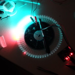
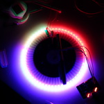
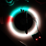
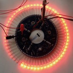
Colourclock
Original concept circa 2008, revisited 2012, hardware designed Feb 2014, firmware designed April-August 2014, project completed August 2014, installed in spare room in 2016, written up in March 2018 (jeeez…)
Acrylic, LEDs, ARM Cortex-M0 microcontroller.
Idea
This has been a long-running project. My notebooks contain sketches of the idea from about 10 years back but I finally made PCBs at the beginning of 2014, finishing construction and firmware late 2014 – and it’s taken me about 4 years to write it up.
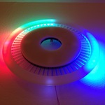
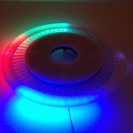
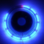
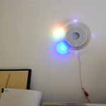
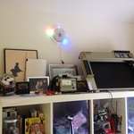
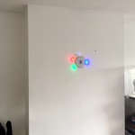
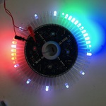
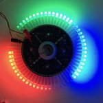
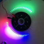
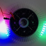
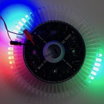
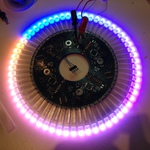
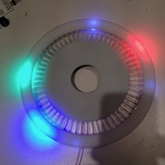
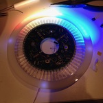
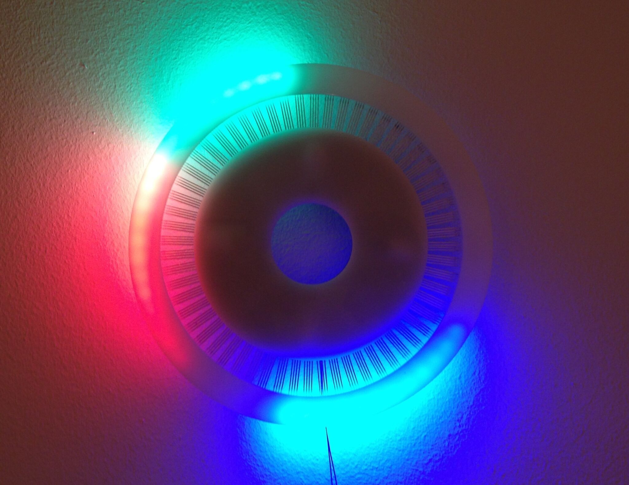
The basic concept is 60 radial RGB LEDs in a circle, with light and colour representing analogue ‘hands’. Where the hands cross, pleasing colours result. Joy. There is really nothing like the solid punchy colours of RGB LEDs! Except, maybe, lasers.
So if you’re colourblind, this might suck for you. Don’t build one. Sorry. If not, build one!
Design concept
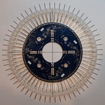
The design is visually simple. It consists of:
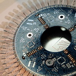
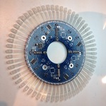
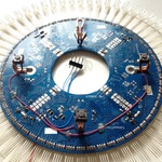
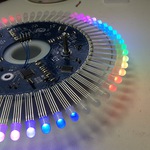
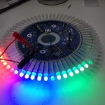
- A ring-shaped PCB, with LEDs mounted around its circumference
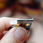
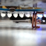
- The LED leads go out radially in the same plane as the PCB and support a ring of opal translucent acrylic, laser cut, glued onto the upper face of 60 5mm RGB LEDs
- The outer ring sorta ‘floats’
- A ring of matching acrylic, screwed onto the front of the PCB
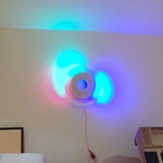
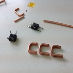
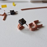
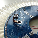
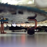
- A set of wire stand-offs, to hang the PCB and to hold it about 1.5cm from the wall
- Three microswitches built into the stand-offs – you activate a switch by pushing the whole clock back onto the wall
The 5V power supply is meant to be chased into the wall. Most of the photos below date from previous test installations, but this video shows it in its final place, with wires buried in a (not yet painted) channel.
There are a number of “faces” to display time in different styles. A core part of the idea is that each R, G or B hand blends together with the others, mixing and making beaucoup de other colours.
Hardware design and operation, PCB layout
Okay, I want a circular PCB with LEDs shooting directly off the edge. I don’t want 240 wires or LED strips. Now what?
Doing the maths showed that if I wanted 60x 5mm LEDs around the edge of a circular PCB, the circular edge would have to be about 110mm diameter at a minimum. Well, Eagle is right out, I figure. The free version won’t let me make a board above 80x100mm.
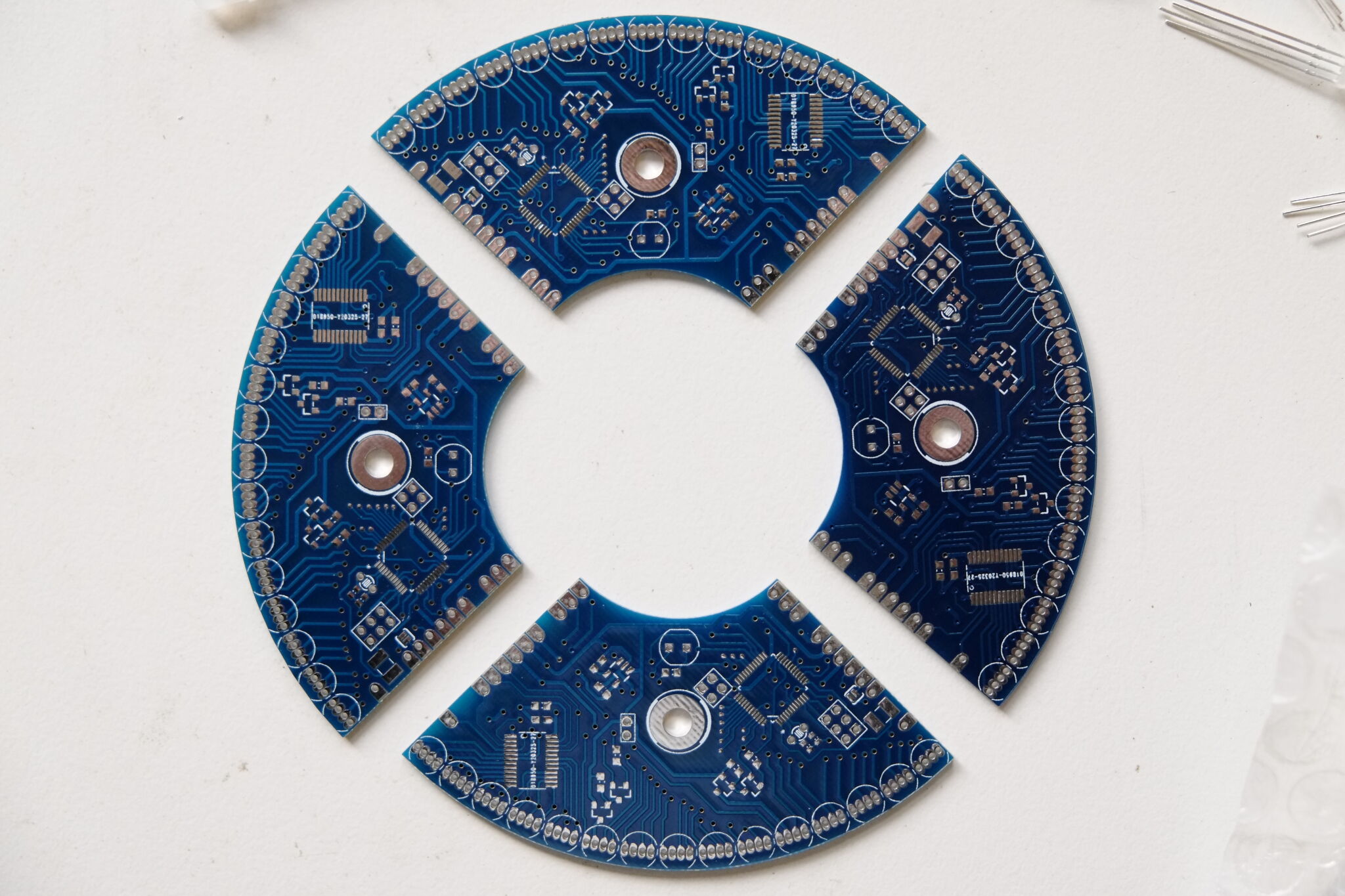
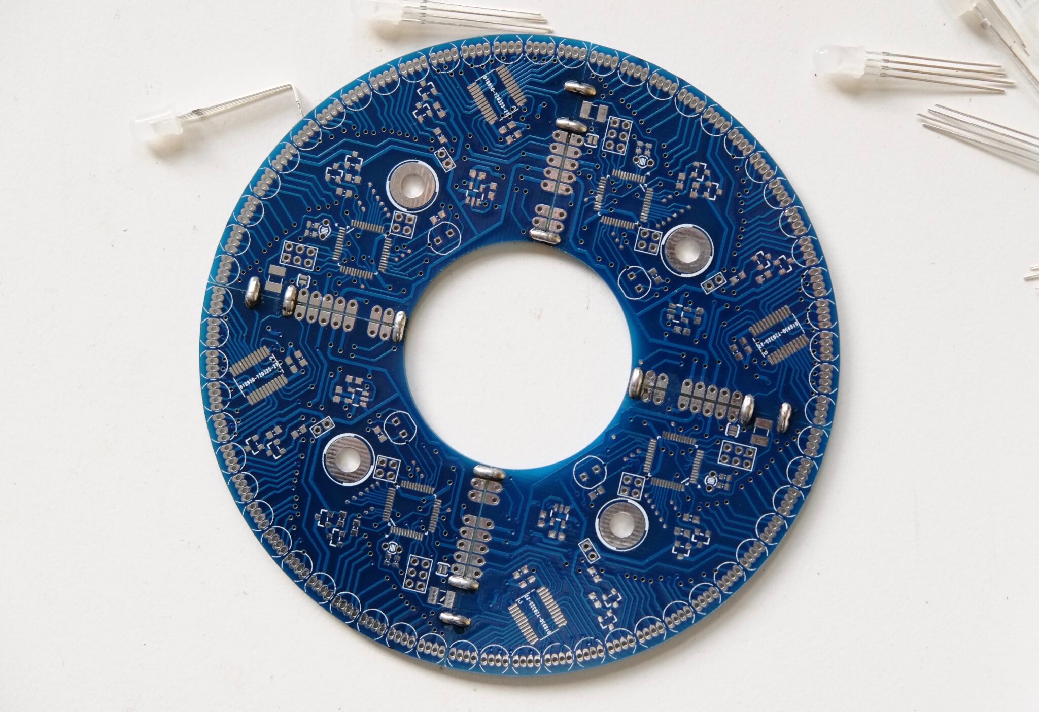
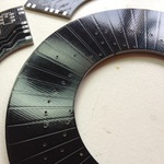
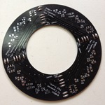
So, I took a different approach by splitting an annular/ring PCB into four boards covering a 90° arc. I designed one common arc-shaped PCB that is used four times, with the board being much smaller than Eagle’s limit.
The second problem is I’m way too lazy to spend an hour typing a list of coordinates into Eagle to move LED footprints into place, so I wanted to automate placement of the LEDs and board outline. However, to avoid having to mess with editing proprietary binary file formats, I needed CAD software with plain-text files. Then I could just wield the Power of Perl…
I looked at KiCad. I looked at gEDA. I looked at KiCad again. (Still on my list to learn.) I ended up abandoning hope, but when Eagle 6 came out (XML file format!), I was back in business.
Circuit operation
There’s a bit that drives the LEDs, and a microcontroller that controls that bit.
Since I was now designing a PCB for a quadrant of the clock, the most practical approach was to design a circuit to drive 15x RGB LEDs and replicate that four times, chaining quadrants together into a ring of 60.
I chose a single-chip 16-bit constant-current driver, which contain a latch and shift register. The first decision was:
- Either drive 15 LEDs of one colour at a time and light R,G,B in sequence,
- or, use one 16-bit driver to drive 5 RGB LEDs (15 LEDs) at a time and light each of 3 groups in sequence.
I didn’t want to risk ‘colour trails’ similar to what you get with a cheaper DLP projector. (They have one DLP device with a colour wheel to display a red frame, green frame, blue frame, etc.)
To resolve this indecision, I prototyped it with a single LED. Though option 2 was going to be harder to route, I chose to use 15 outputs of one 16-bit driver to illuminate one third of the RGB LEDs in a quadrant at a time – with three MOSFETs to select which third to illuminate. It’s fairly subjective, but in this design the colours look better to my eyes and I sleep that bit better at night.
In the assembled ring, each quadrant’s 16-bit driver is a shift register that chains through neighbour quadrants, making a 64-bit shift register driven by SPI. There are three MOSFETs per quadrant and these are driven by three common gate signals.
I took some time to choose a microcontroller, weighing up:
- Price
- DMA abilities to SPI for the shift registers
- Desired colour depth and refresh rate, therefore requirements for SPI speed, CPU speed and RAM
A deeper colour depth (more PWM bits) influences how much CPU time is spent calculating display bitstreams, how many bits need to be shifted out during a frame, and how much RAM is used for buffering it. With a non-infinite SPI clock rate, you trade off refresh rate for colour depth.
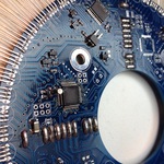
I ended up with the STM32F051C6T6, a 48MHz ARM Cortex-M0 with 32KB of flash and 4KB of RAM. This is a really cool microcontroller, especially when using DMA. Though it doesn’t sound worth it, the firmware uses DMA to clock out the 64 bits of state for one scan of the LEDs using DMA, because then the code doesn’t have to busy-wait on the SPI send register and can save a significant amount of CPU time. (It’s triggering the SPI output in an interrupt, too, so avoiding busy-wait is especially important.)
The display drivers also have a handy /OE output enable pin, which acts on all outputs. I’ve used this to provide a global brightness control by wiring them all to a fast timer PWM output on the STM32. Whilst the CPU is generating scan data to PWM the LED driver pins individually, the output enable PWM runs much faster and further modulates the LED drive. For example, if the CPU through SPI says that one LED is on for 1 out of 64 ticks, a 20% duty PWM on the /OE pin makes it 20% as bright again.
The microcontroller uses its internal oscillator and PLL for general operation, freeing the external oscillator for use with a 32KHz watch crystal to drive the RTC.
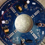
Some of the STM32’s ADC input pins are broken out onto a header for interesting sensors. As an experiment, I built a ring-shaped capacitive touch sensor that plugs on top – the idea was that you could ‘dial’ to set the time. It worked OK, but the practical sense distance (to a fingertip) is too low to work through 3mm acrylic – so the final design uses bog standard switches for input. Another analog input measures ambient light levels with an LDR.
The rest of the circuit is LDO and decoupling.
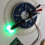
View a PDF of the schematic. There’s one annoying error on the RevA board: I brought out the SWD pins to a 4-pin header for programming, along with ground and Vcc. Instead of Vcc, I should’ve wired /RESET (which is useful for programming). I tend to bring out things like /RESET to test pads even if there’s an on-board reset circuit, so for programming this can be poked with a pin, but it’s not as convenient as just one connector.
Board layout
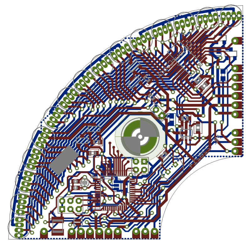
As mentioned above, I automated the initial placement of the LEDs and board outline by generating XML into the Eagle .brd file using a perl script. Rather than being a sledgehammer for a nut, this turned out to be really flexible as I could very easily re-place the LEDs on a different radius, or with different spacing, to tinker with the overall size whilst routing the board.
The boards are all populated in an identical way except for the first board which is also populated with the LDO regulator and microcontroller/crystal. Each board joins to its neighbours with large pads that route common power, MOSFET gate signals, clock and latch signals, plus pass the dataOut of the shift register on one board into the next board’s dataIn.
I managed to route the signals such that the board could be an arc shape rather than a full pie-wedge, leading to ring-shaped megaPCB when assembled. It’s still a bit wide for my taste, but it was the best I could do with a 2-layer board.
See the Resources section for CAD files.
Software
With a powerful uC and 18-bit colour, there’s good potential for smooth transitions and nice blending. I didn’t end up doing any really busy ‘sparkle’ or watery/physics-style effects in the end, opting just for simple variants on red for hours, green for minutes, blue for seconds. I tried some more busy effects, but it was hugely annoying to look at – less is more.
The firmware implements PWM at 6 bits per channel (262K colours) by flattening RGB framebuffer values into a raw bitstream of ‘on/off’ values that is streamed through the shift registers at 24MHz. At this bit depth, it refreshes the display at 300Hz (meaning it completes a full 6-bit PWM cycle for all ‘thirds’ at 300Hz). Altogether, this uses around 29% of the CPU time for display.
This flattening uses a lot of memory. 64 levels per channel for 3 channels for 60 LEDs equals 1440 bytes of buffering to flatten out the framebuffer into a format that the DMA/timer IRQ handlers can just spit out through SPI, and then that’s double buffered. (Note that it doubles for each extra bit of colour depth!) The alternative of calculating the PWM on/off state of each LED in the IRQs sounds reasonable at first, i.e. perform the conversion piecemeal instead of doing it all upfront every framebuffer update. However, it saves a lot of CPU time to burn the RAM on a buffer and calculate it only when the framebuffer is updated, especially since the framebuffer update/animation rate is usually way less than 300Hz. There is a better alternative again still: Binary Code Modulation would allow the IRQ frequency to be drastically reduced to 6 per frame (with a variable/exponential time delay between IRQs) instead of 26, and would save most of that burned memory – I used PWM here to keep it simple, but have used BCM in other LED projects. (Watch this space.)
Reality bites: I found the MOSFETs don’t turn off that nicely, so some ‘thirds’ bleed into the next-displayed ‘third’. This is worked around by simply adding some dead-time to the scan, so one FET can settle and switch off before the next scan data arrives. This negatively affects the overall refresh rate, but significantly reduces the bleed between unrelated LEDs.
I didn’t bother with gamma correction for the framebuffer output, since the sine-wavey gradients written into the framebuffer had a similar effect.
The 6 bit colour looks good – good enough, at least – but the 300Hz update looks wonderful!
Scaling brightness
LEDs are punishingly bright. Even with just 60 of them, the clock is enough to light up the room a fair bit. The /OE signal is PWM’d, as described above, and the firmware controls this using the LDR’s brightness measurement. There’s also almost zero CPU overhead to this dimming technique, because it’s applied by a free-running timer PWM output. The /OE signal PWM rate is about 93KHz (faster than the colour-generating PWM) so it doesn’t cause visible ‘beats’ in the output brightness.
There’s another UI mode included in the firmware to set upper/lower brightness thresholds, to adjust the LDR response to a room. These parameters are stored in flash using a trivial journal/log technique to reduce the amount of flash erase wear and tear on an update. Given I’ve changed this exactly twice, it’s overkill, but still a fun thing to try.
Simulation build
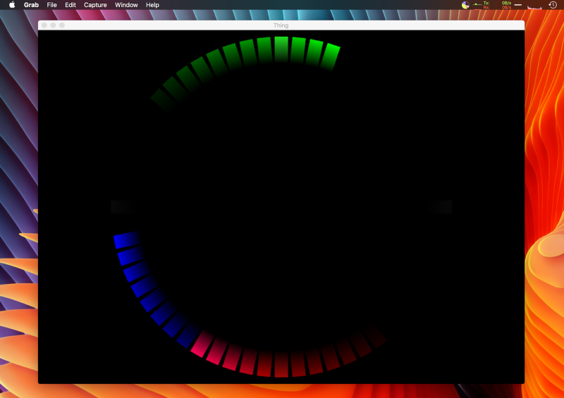
Tinkering with the display styles took a lot of hack-compile-test cycles, which was a bit slow to do on real hardware. (I also wanted to start before I’d finished soldering.) So, I added a build target to build the firmware as a regular Linux/MacOS binary, swapping the LED drive and STM32-specific code with an SDL/OpenGL front-end:
I’ve used this technique in other microcontroller/embedded projects and it’s been really useful. Give a little thought to abstraction and interfaces, and you can build a harness to test/run/develop your firmware natively on your laptop.
Resources
- Eagle design files for schematic and PCB layout: https://github.com/evansm7/colourclock-hw
- Firmware sourcecode: https://github.com/evansm7/colourclock-fw
Gallery
- Colourclock, test mount
- Icy minimalist time...
- New room, pre-decoration
- LEDs bent to same dims
- Positioning LEDs against pattern
- All soldered
- Making standoffs/feet out of wire
- Feet against wall, with switches
- Rear assembled, 3x switches and hoop
- View in back
- Some bodged-on extra decoupling...
- First test, no smoke!
- Exotic colour mixes
- Test of 64-level brightness
- Capacitive touch sensor
- Nice idea, but wasn't sensitive enough.
