3D graphics on an ancient scope
Because it’s cool! Vintage hardware! The smell of 1970s electronics! Star Wars (™, ©, ®, etc., George don’t sue me, call it fan art…)! AVR! Programming!

With my keywords out of the way, some words about the project:
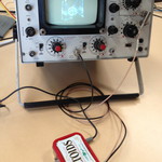
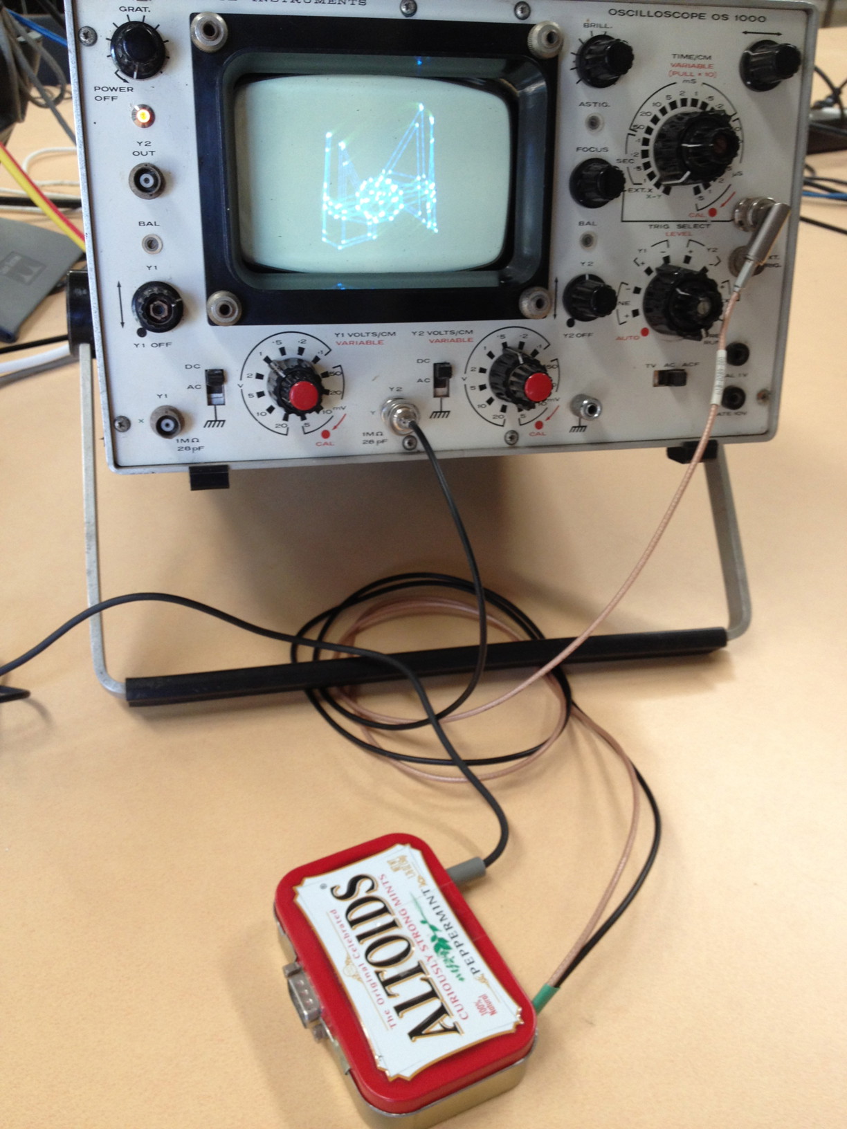
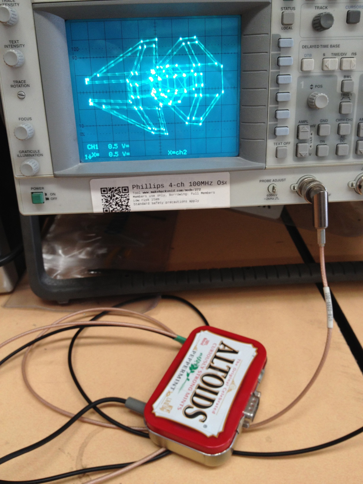
This project uses a Maxim 10-bit dual-channel Digital to Analogue Converter driven by an AVR ATmega88 to move the electron beam around the screen of a circa-1970 oscilloscope in X-Y mode. With some R-C filtering on the DAC output to slow the rate of change, a line is drawn between two points when the DAC output is changed.
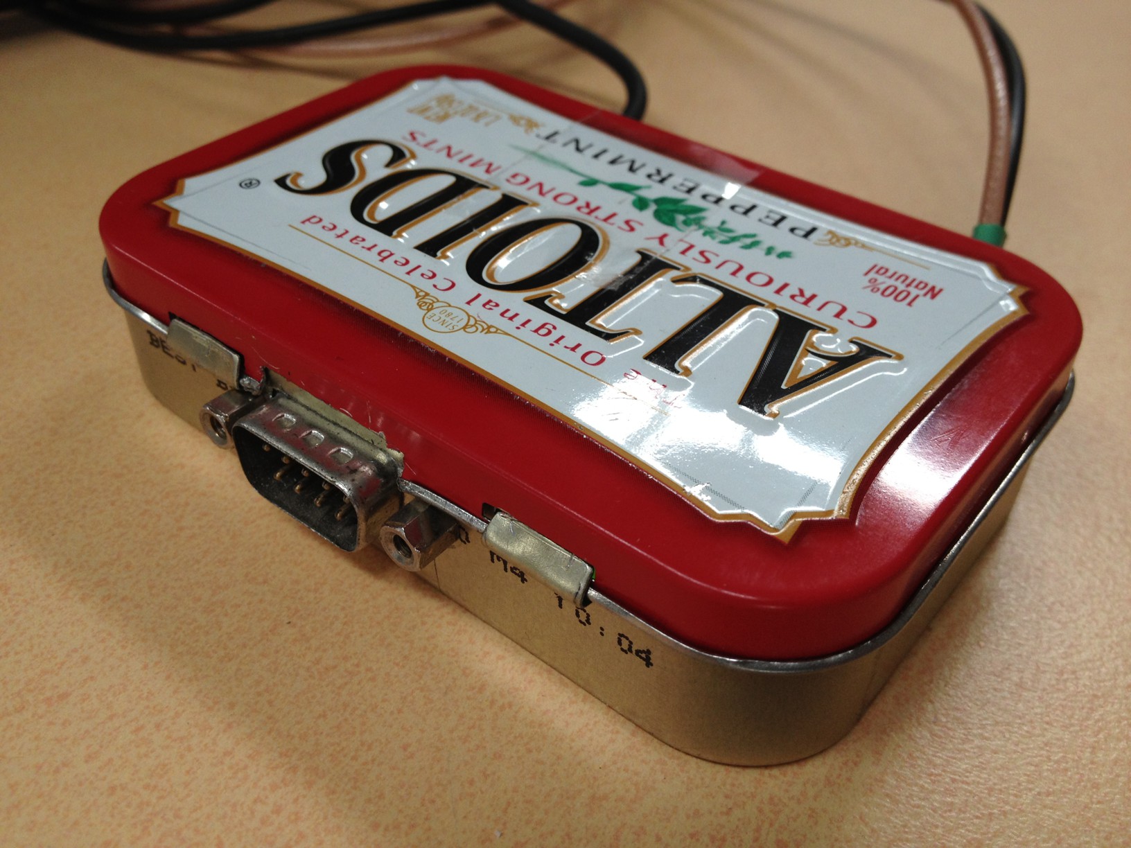
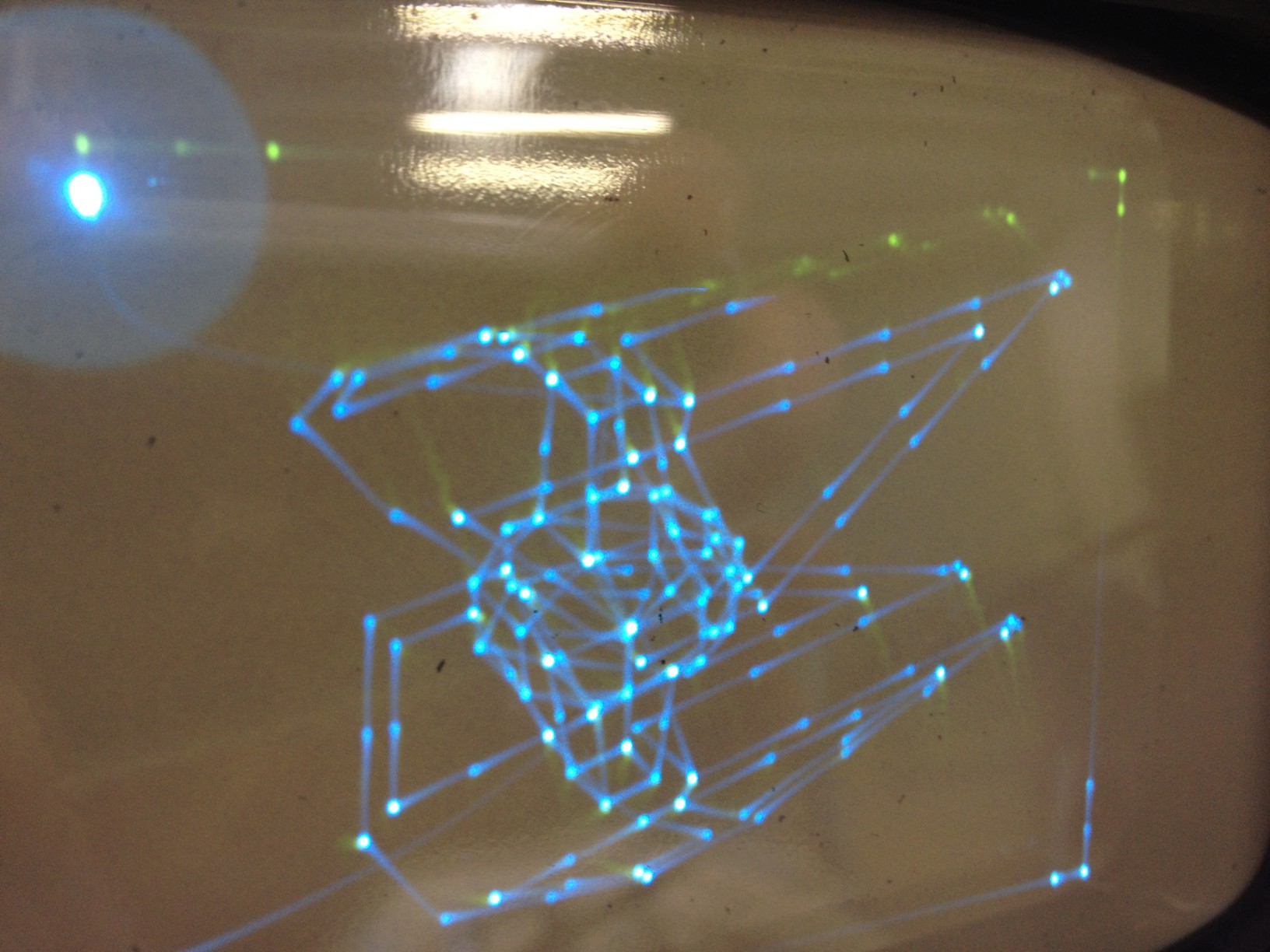
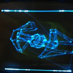
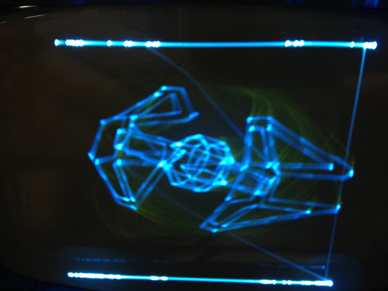
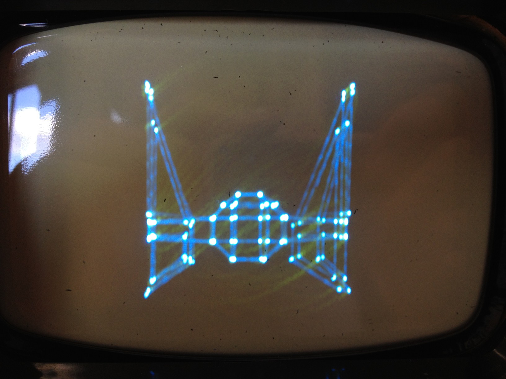
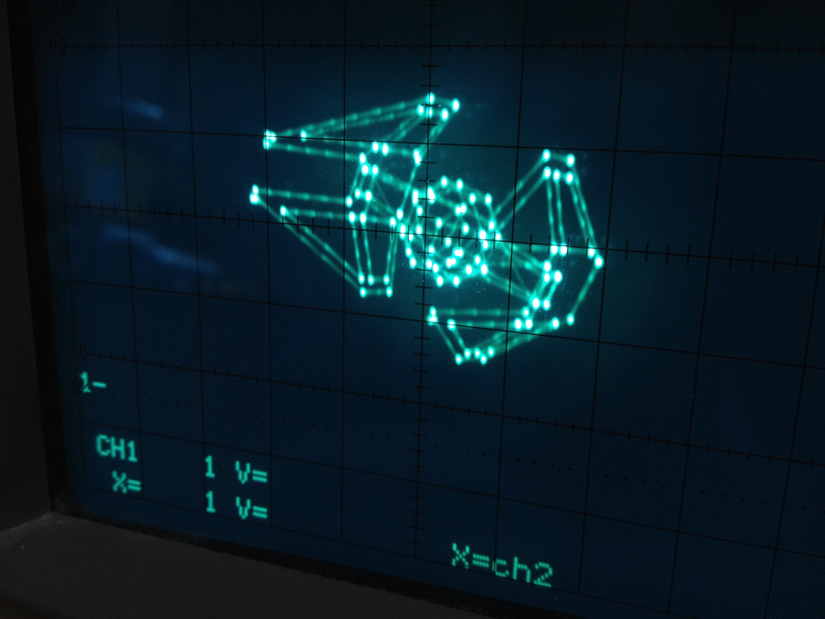
A program reads ‘model data’ from flash, or RAM, and transforms/rotates the 3D coordinates. Then, lines are drawn between points on screen. If lines are longer than a certain threshold (chosen artistically) the lines are subdivided into smaller lines, i.e. intermediate points/DAC steps. (I found it just looked better this way.) The end result is an Altoids tin with a power socket, an RS232 socket and two cables with BNC attachments to the scope – on power-up it draws an ever-tumbling TIE Interceptor spaceship.
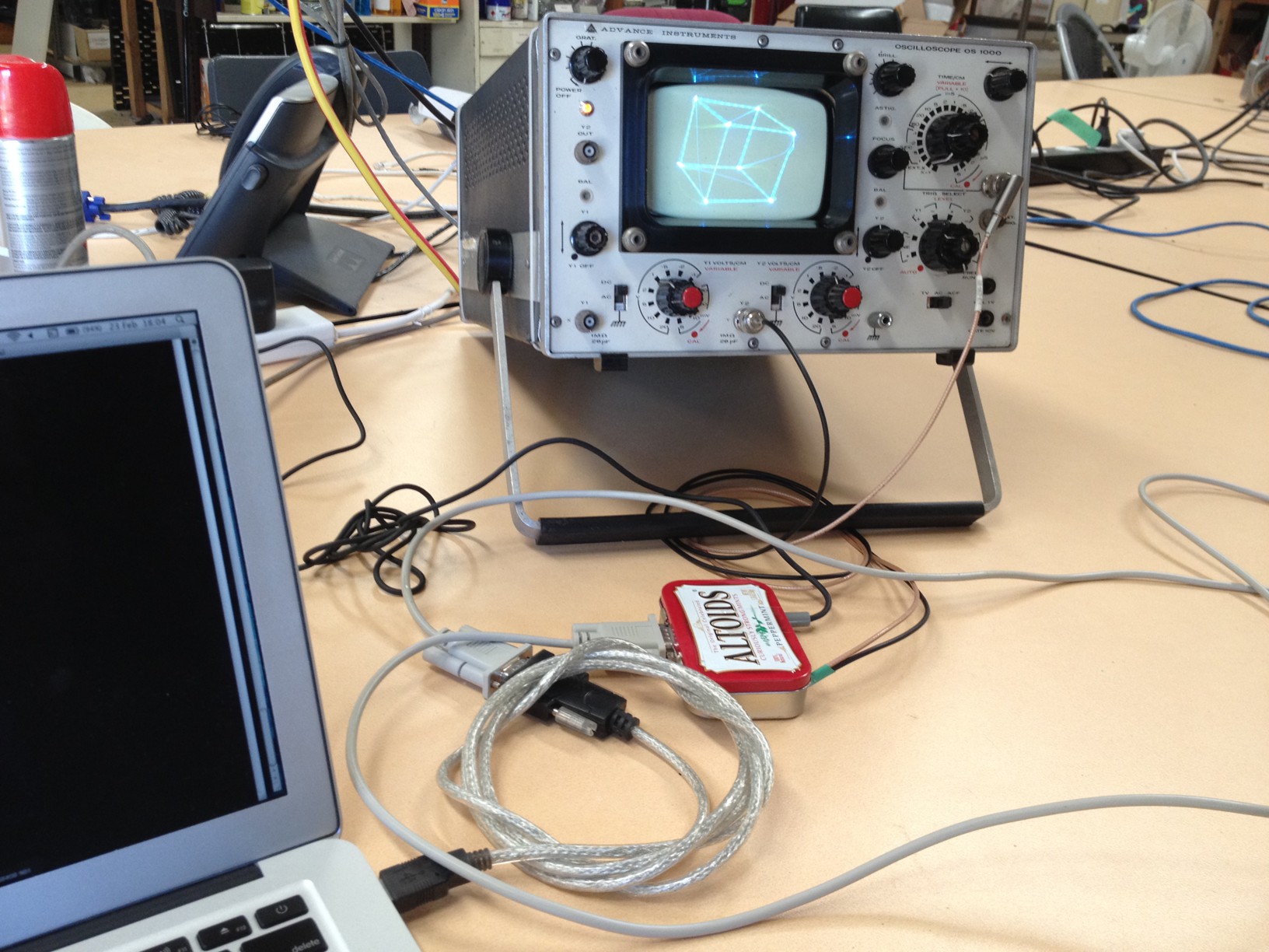
The RS232 port enables a host PC to control the rotation, select different models (currently only the ship plus a cube) and, most usefully, to download 3D data into RAM and display that.
Drawing lines
The project was a bit of an experiment, as most of these things are. I found that (duh, obvious when you think about it) just attaching the DAC outputs straight to the X-Y inputs of a scope didn’t work well. If I gave the DAC a series of points all I’d see were dots at those points; that is, once the DAC latches a new value and converts it, the output changes (i.e. dot moves) far too quickly to see a line. The dots are where the electron beam sits while the processor calculates the next point, with no visible line between.
The solution to this was to hook up a first-order low-pass filter to each output. Basically, DAC output drives a capacitor (to ground) through a resistor. Very fast changes at the DAC output (i.e. high slew rates) are high frequencies; these are filtered/smoothed. Another way to look at it is the voltage across the capacitor increases or decreases “slowly” because it’s driven through the resistor, and the scope beam position is taken from this capacitor voltage.
I spent a while fretting about the 1/(2πRC) maths behind this filter then received excellent advice from a trained electrical engineer – don’t bother calculating it & trying to predict 3db cutoff frequencies etc., just choose a capacitor in the right ballpark and use a variable resistor. Then just tune it until it looks right. This method is right up my street. :-)
Drawing 3D stuff
I rewrote/re-hacked the code a couple of times, changing my mind about how to draw the lines. Initially, I had two passes; calculate the 3D rotations/perspective transformations into a set of 2D points, storing these in RAM and the second pass reading the list of points to traverse and actually moving the electron beam through them.
The advantage of doing all your calculations first is that you can store your model data as a set of points plus lines/polygons referencing those points. If you have any point that a number of lines touch (e.g. the corner of a cube) you are only doing the maths on that point once.
Unfortunately, this uses a lot of RAM (the ship model has ~150 points, at 2+2 bytes per point that’s over half the RAM gone) but also means there’s a lengthy pause while you calculate the next frame. I just blank the scope beam during this time. Works nicely on the ‘dev’ scope, but the Z-axis/blanking input of the vintage scope is kaput. No blanking for me. I read the schematic and gingerly poked about at the back of the scope to fix it but honestly, I have little high-voltage bravery and left the scope as-is.
So – the long calculation delay causes the beam to sit still and create a super-bright spot. It’s distracting and bad for the phosphor so I chose a different method:
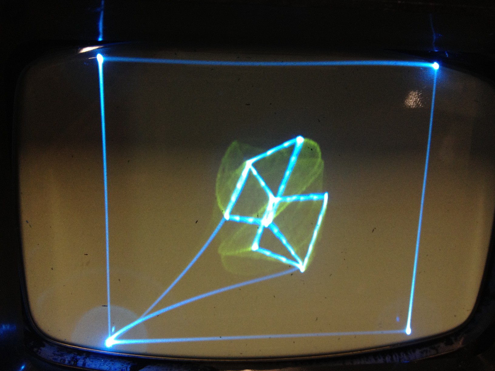
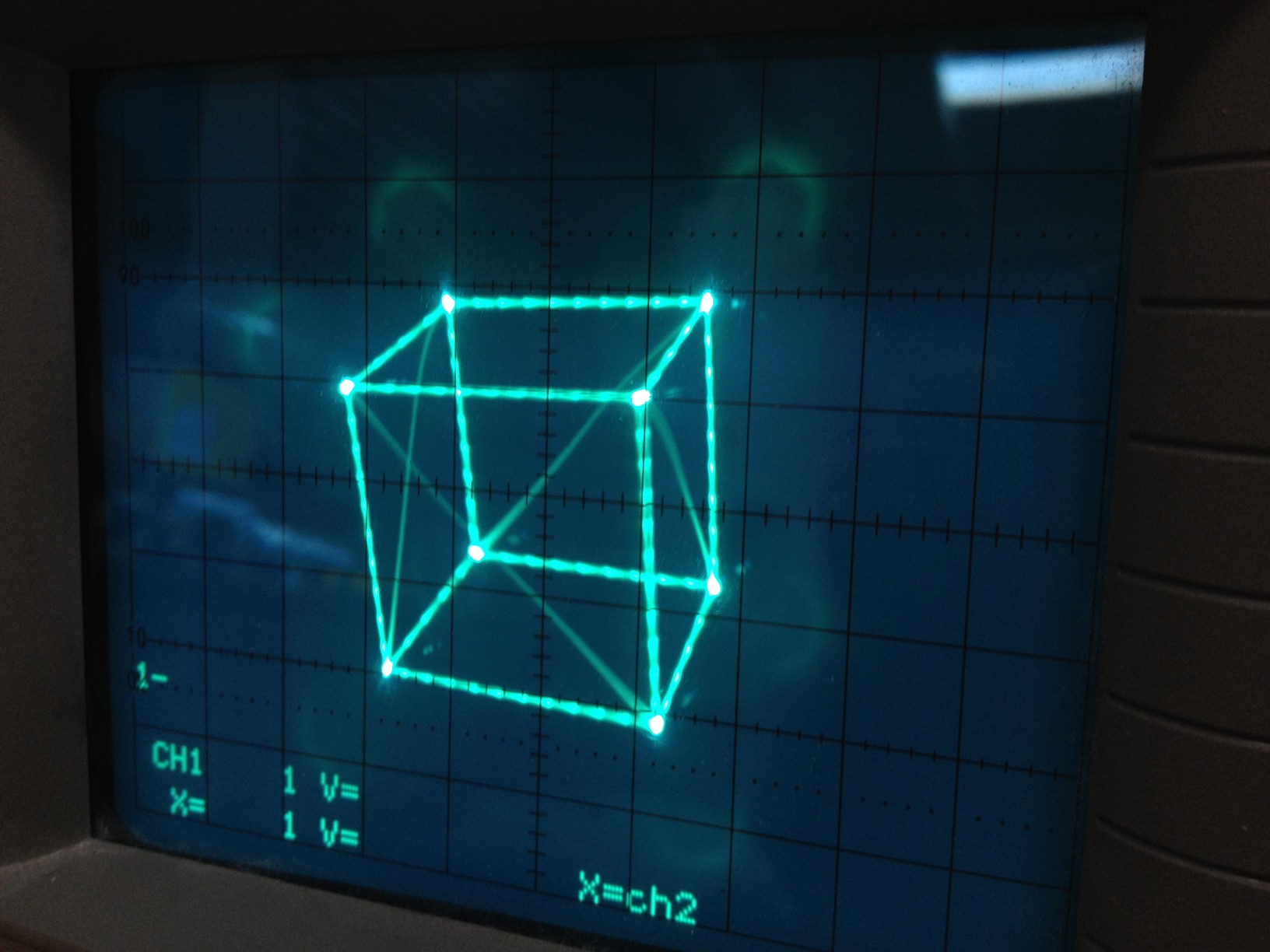
The models are stored in a less-efficient ‘line strip’ format; a list of coordinates is provided with, roughly, “draw to” and “move to” tokens between them. This is less efficient in terms of compute time; think of drawing a cube like this, where corner points will be passed through more than once therefore be calculated more than once. So, it’s slower; but, the advantage is that you can be moving the beam while you calculate. As it’s drawing as it thinks, there is no need for the beam to sit still burning a hole in the screen in a ‘calculate’ pass. There are brighter points at each line end, which correspond to the beam ‘lingering’ as the next point is calculated (which takes noticeable time). But, I think the ‘constellation’ effect is quite nice. And since the lines are drawn whilst points are calculated, no RAM is required to store intermediate points, thus all the RAM is now free to download models via serial.
The model itself was drawn on graph paper and then coordinates typed in, for a total of 144 lines. Tres 1980s! Anyway, the lines are drawn in an order that hides the fact that there is no Z-blanking. The retrace is pretty much invisible, especially when it’s moving.
Other notes on the firmware:
- Uses the Cohen-Sutherland line clipping algorithm (with 16-bit intermediate coordinates) so models crossing screen edges look correct
- All transforms done using fixed-point integer arithmetic with carefully-chosen integer size. 32x32 multiplies are slllloow on this 8-bit machine, so prefer smaller multiplies (choose C types carefully).
- sine/cosine are done with a lookup table of 0-90° in flash, mirrored/negated as appropriate for other quadrants
- Divide accelerated with fixed-point fraction lookup table for common values, falling back to C divide for less-common values
Hardware
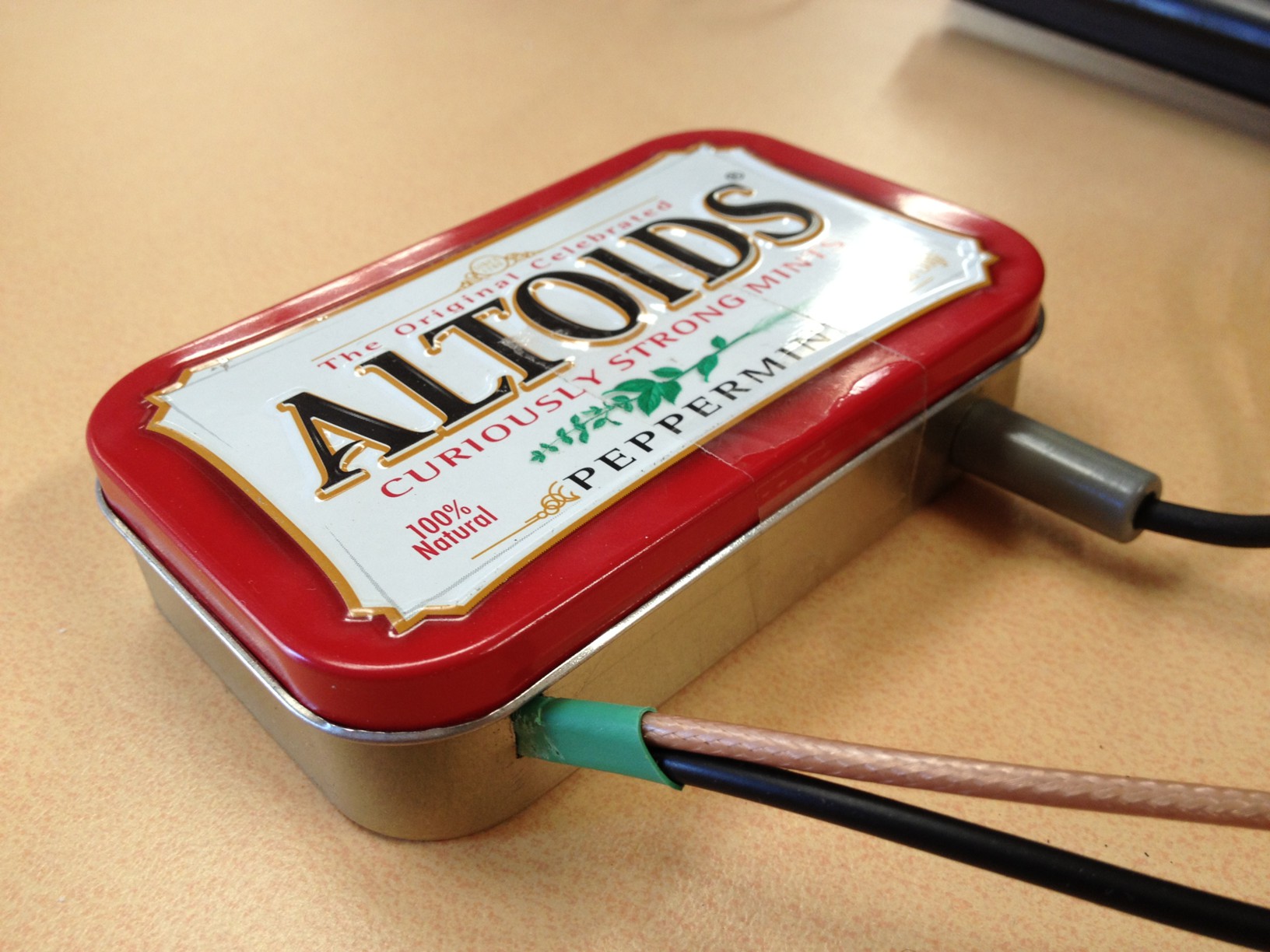
The hardware is filthy, so there are no photos of it. I’d used the MAX5159 on a scrap of stripboard for a previous prototype and reused this scrap with another piece housing the ATmega88. It’s really incredibly basic though…..
- ATmega88 @ 20MHz
- SPI connection to MAX5159 DAC
- 5V regulator for main supply, 2.5V regulator for DAC reference voltage
- 2x R-C filters, one on each DAC output channel. From memory, 100k pot plus a 1uF capacitor.
- MAX232 for RS232
- Loads of sticky tape and bits of paper to stop everything shorting out on the bastarding Altoids tin. It really seems like a cute enclosure but metal metal everywhere and sharp pins poking through tape wasted lots of time.
Software
Bask in the unclean glory here: scope_3d_1.0.tgz. (If you use it, drop me a line, it’d be great to see your vector goodness.)
The purpose:
Adam of Make, Hack, Void is making a barcode hackerspace drinks fridge system and I foisted this upon him as an output device. Hopefully we’ll see something great from him soon!
Built February 2012
Images
-
- Overview of the system
-

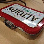
- Housed in the traditional way
-
- Serial port for control
-
- Vector data provided via serial
-
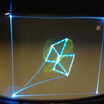
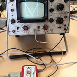
- Early cube test
-
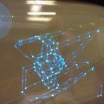
- Early TIE test
-
- Early TIE test (lines from no blanking)
-
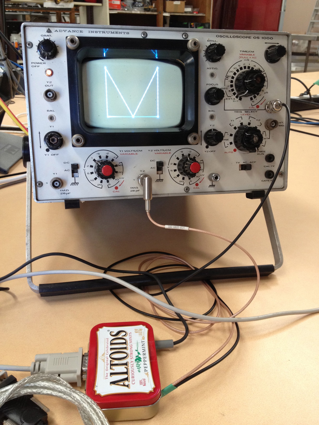
- Slightly sharper on the non-vintage/good scope
-

- Test cube (on the good scope)
-

- TIE fighter on the good scope

Video
Video of the delightful 3D nature of the output: