My Nixie clock
Yet another Nixie clock…?
I think I’ve seen about 1000 Nixie clocks on the net, as everyone seems to build one. But then, I found some Nixie tubes in a surplus store and once I saw them lit, I (inevitably) designed this clock.

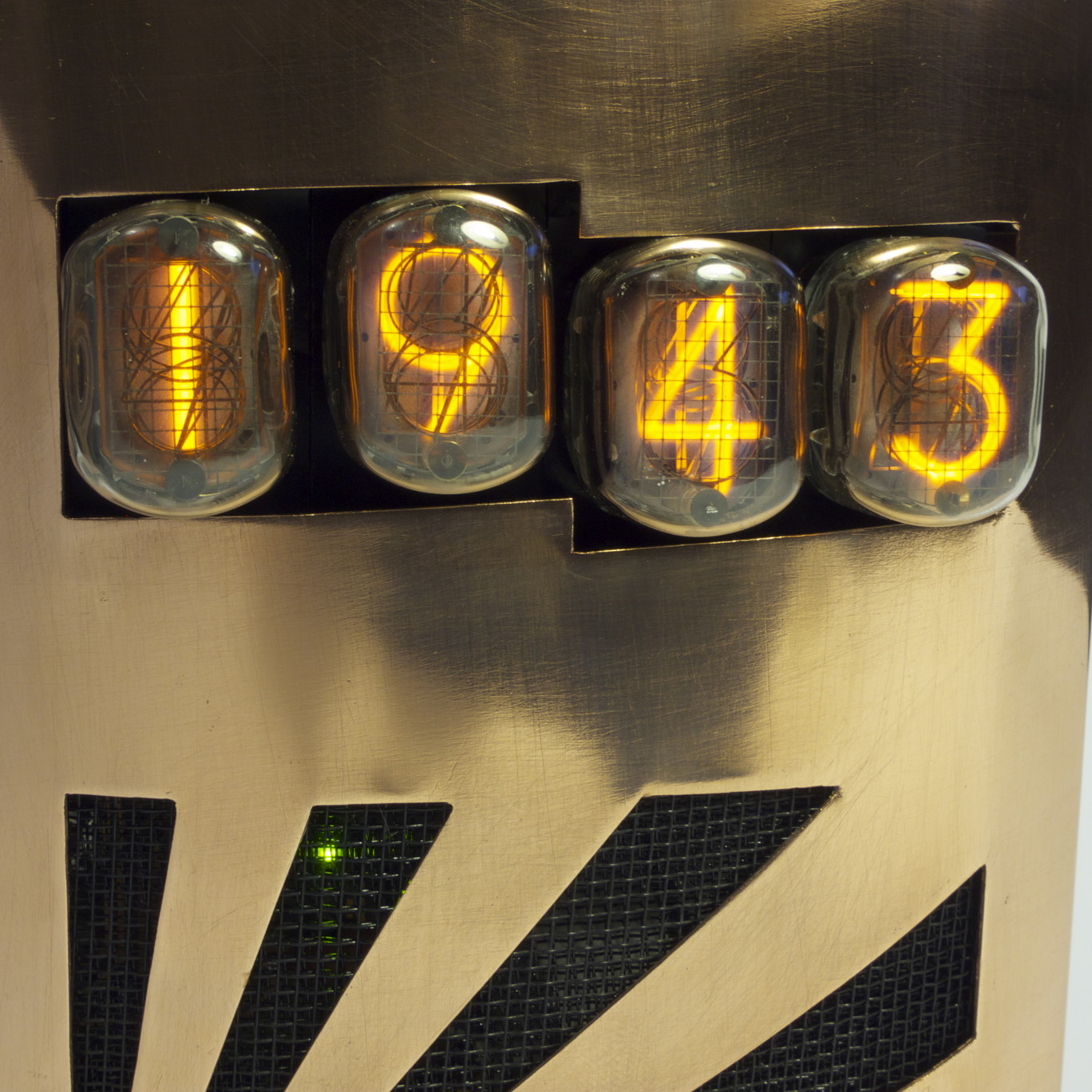
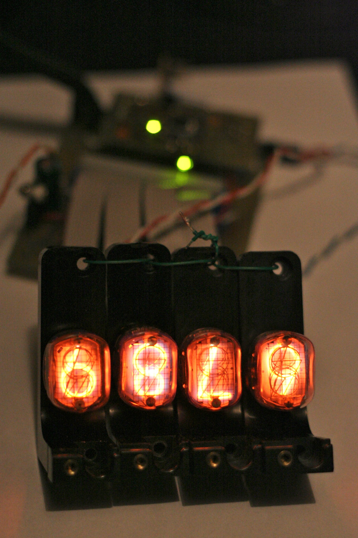
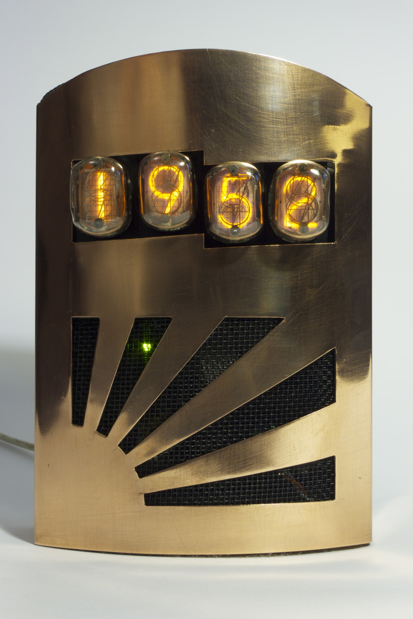
For those who haven’t seen Nixies before, they’re a display technology introduced in 1955. They are glass devices containing metal cutouts of digits (in this case 0-9) which, when given 180 volts, glow a nice orangey/pinky/purpley glow. It seems impossible to take pictures of their colour; something about the frequencies of light they produce make the numbers look yellow or orange, but they’re much nicer in person.
This clock was started in 2007 and finished in 2011… Initially, I completed the high-voltage driver and control PCBs. Once the clock worked, was settable and kept time (!), it went into an ugly temporary case. It was housed this way for over 3 years; finally, at the Make, Hack, Void workshop, I made its final case and completed the project. (This is rare.)
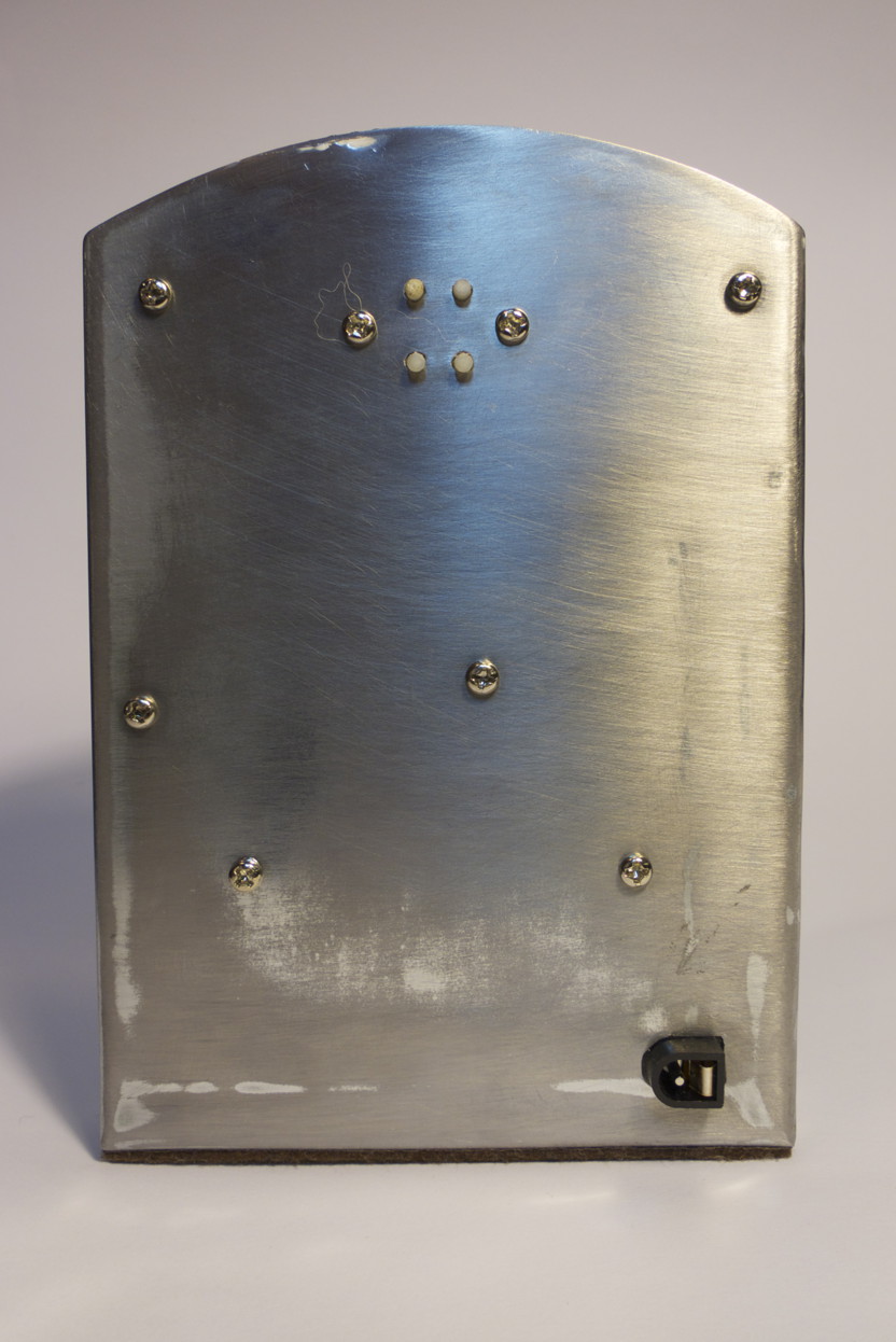
It’s powered from an old 12V iPod power supply and a light sensor lets it dim itself in low ambient light, or switch off completely in darkness. (It’s designed to be a livingroom/kitchen clock rather than sleepy-time clock, so the tube life is extended by powering them down overnight.) Little clicky buttons on the back set the time (or alter a time calibration setting).
Nixies and electronics
I found some B-5991 tubes (dating from 1968), having never seen Nixies up close before. The glow, the glow! I had to make something with them. These are front-view tubes, and arguably the cheapest/nastiest tubes. Ah, well, they still need attention too, so I used them.
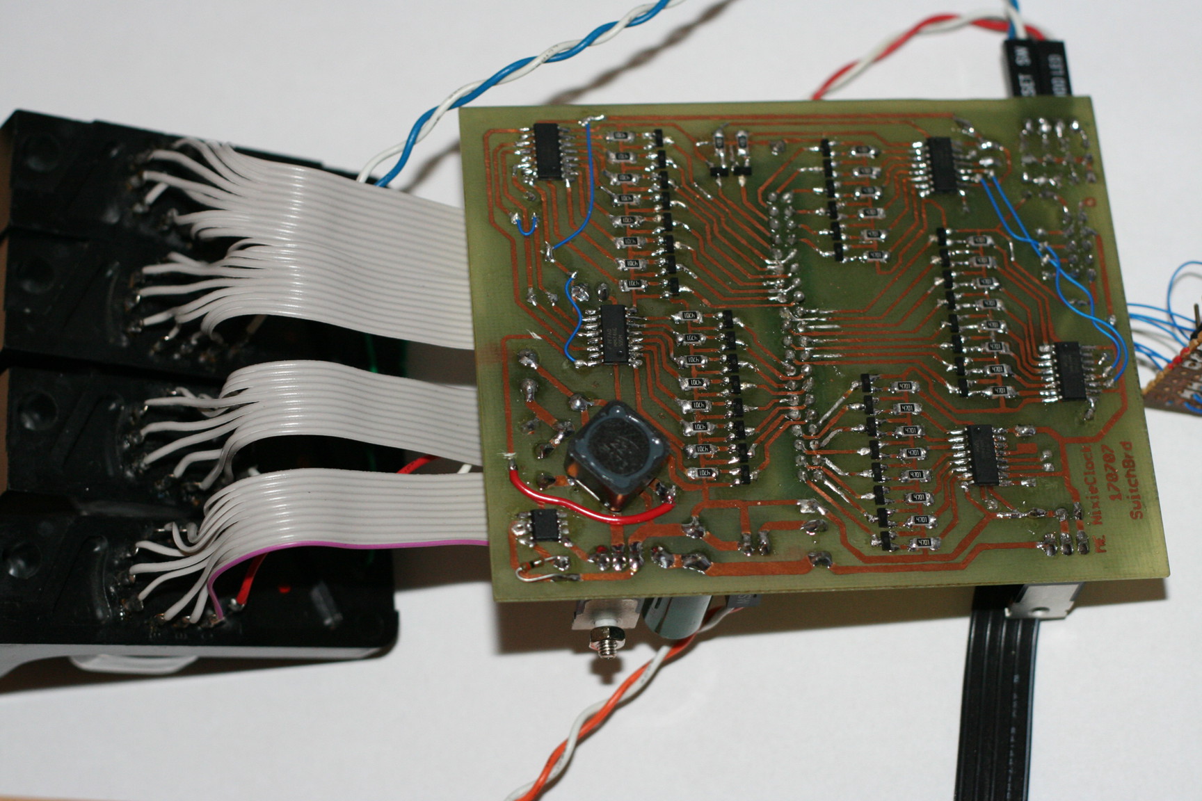
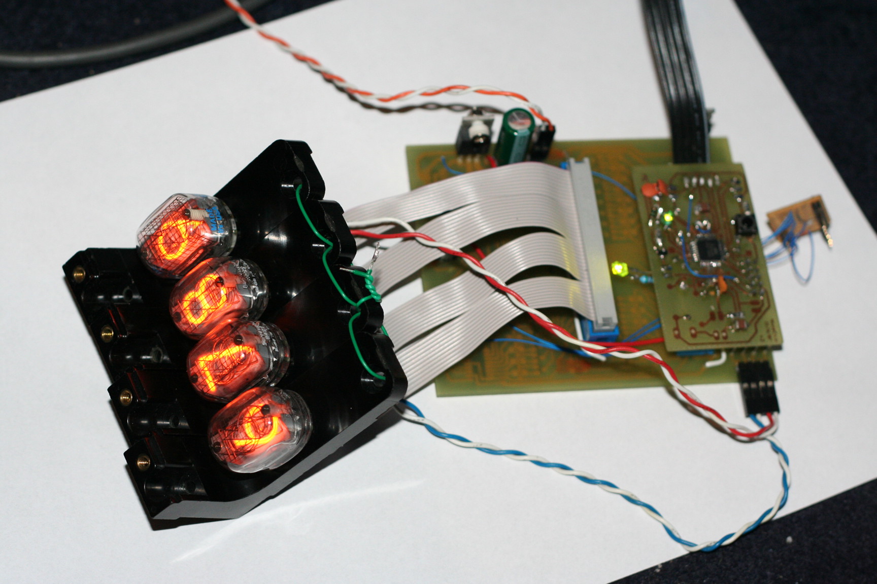
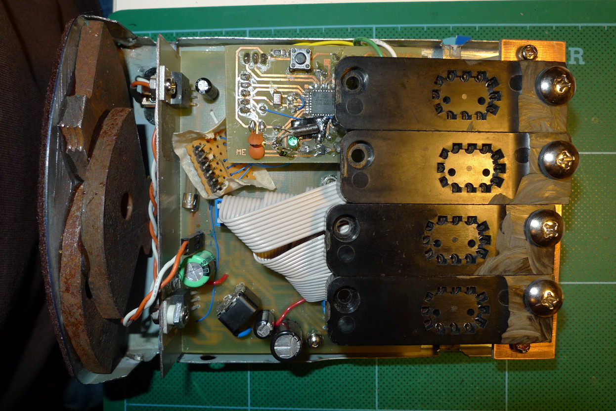
The sensible thing to do is to use some high-voltage driver chips, e.g. 74141s which combine a BCD decoder and high-voltage transistors. I didn’t have any of these, so used a string of 74HC595 serial-in/parallel-out shift registers with some MPSA42 high-voltage NPN transistors. The segments of the tubes are pulled to ground with the MPSA42s (40 in all), which are driven by the outputs of the shift registers.
A separate PCB contains an ATMega48 to drive the whole affair. This shifts bits serially through the ‘595s to select digits to light and keeps time with an external 32KHz watch crystal. Initially I had naively used an external 3MHz crystal to both clock the AVR and generate a timekeeping tick – but such crystals are designed for short-term frequency accuracy rather than long-term, and the time drifted horribly. A better solution is to clock the AVR from its internal oscillator (~8MHz) and drive a timer with the watch crystal, for long-term RTC accuracy.
The power supply is a switch-mode boost converter, generating 180V. It is driven by an AVR PWM output, and a voltage divider provides feedback to an AVR analog input. The loop allows the AVR to regulate the voltage. Choice of components is very important here; the diode should be as fast-recovering as possible (lowest switching time), the output capacitor should have as low an ESR as possible and the MOSFET should be both fast-switching and have a low on-current. The LadyAda boost converter calculator is useful!
I do plan to present schematics here, but they (like the sourcecode) will need some tidying up first. Really, though, there’s nothing particularly wacky in this circuit.
Case
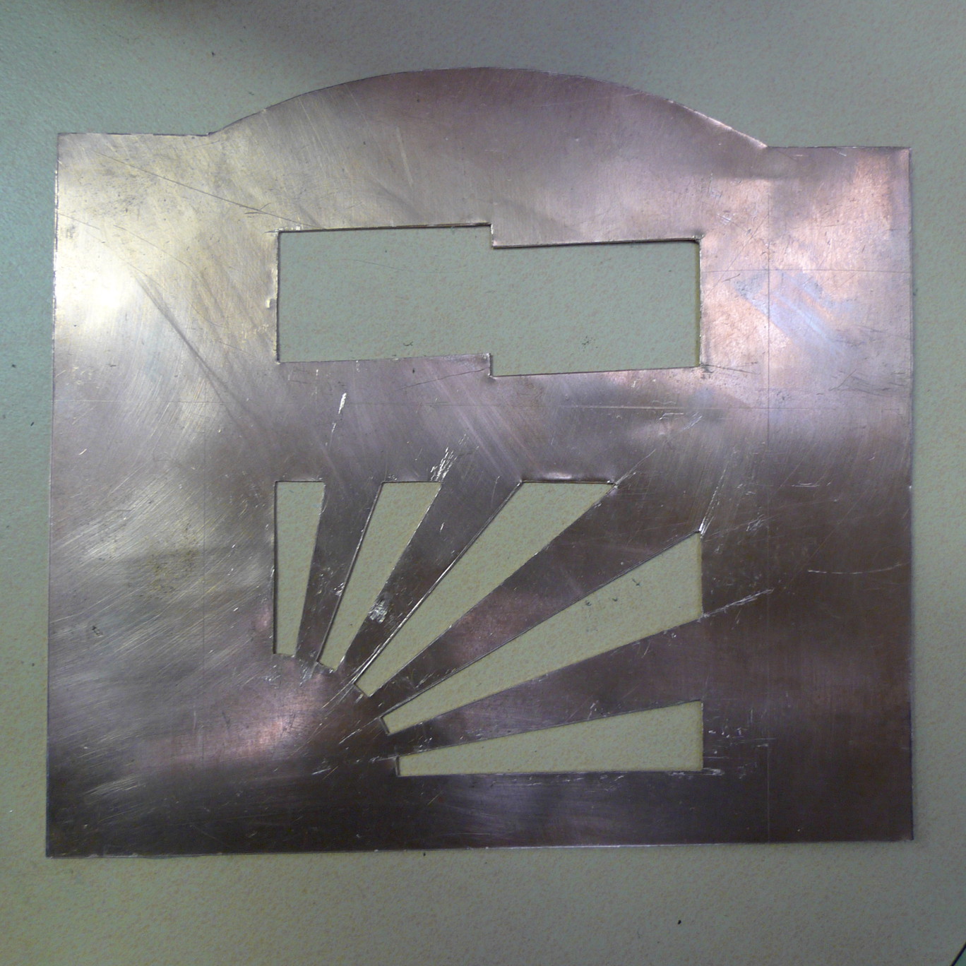
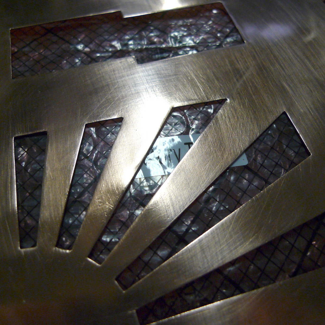
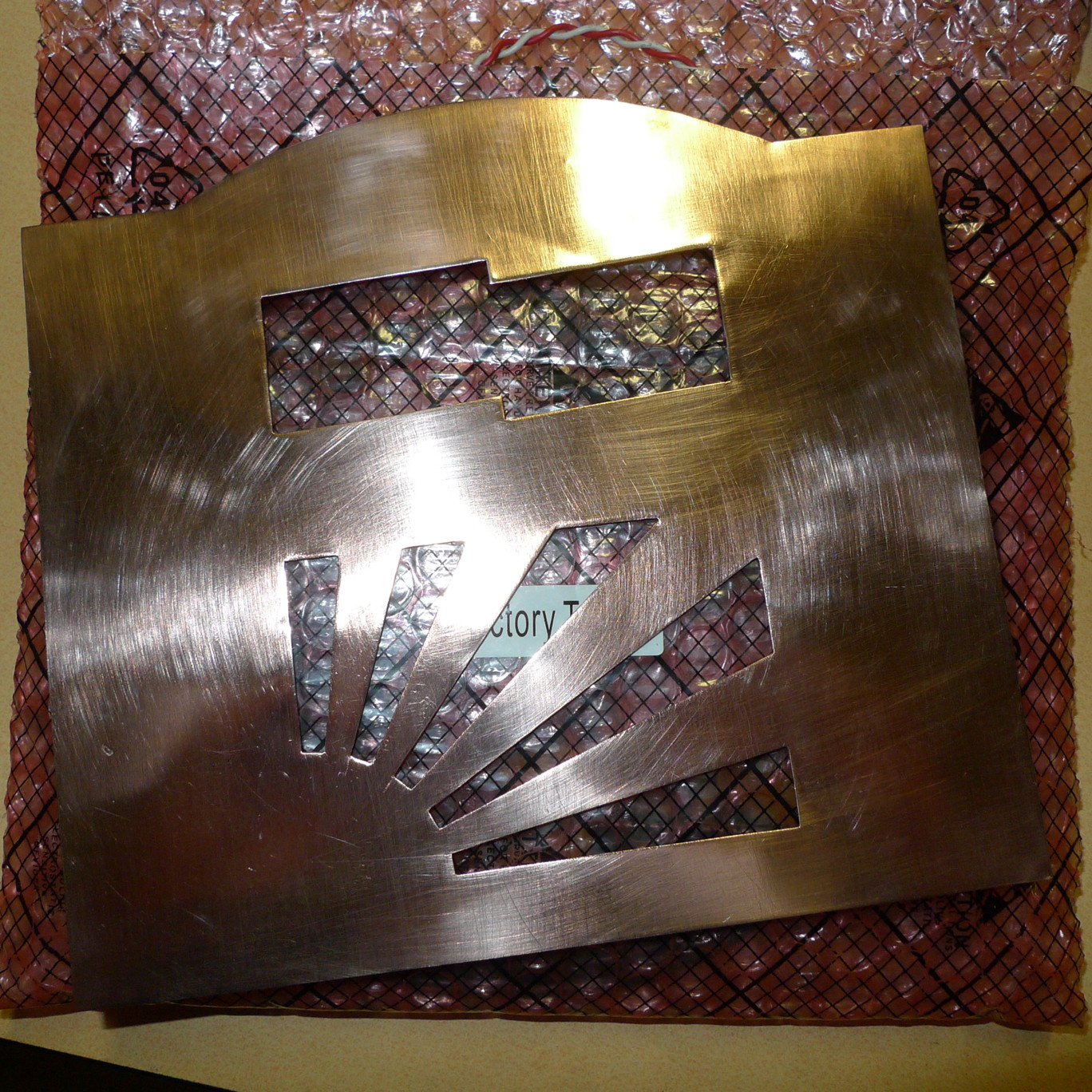
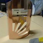
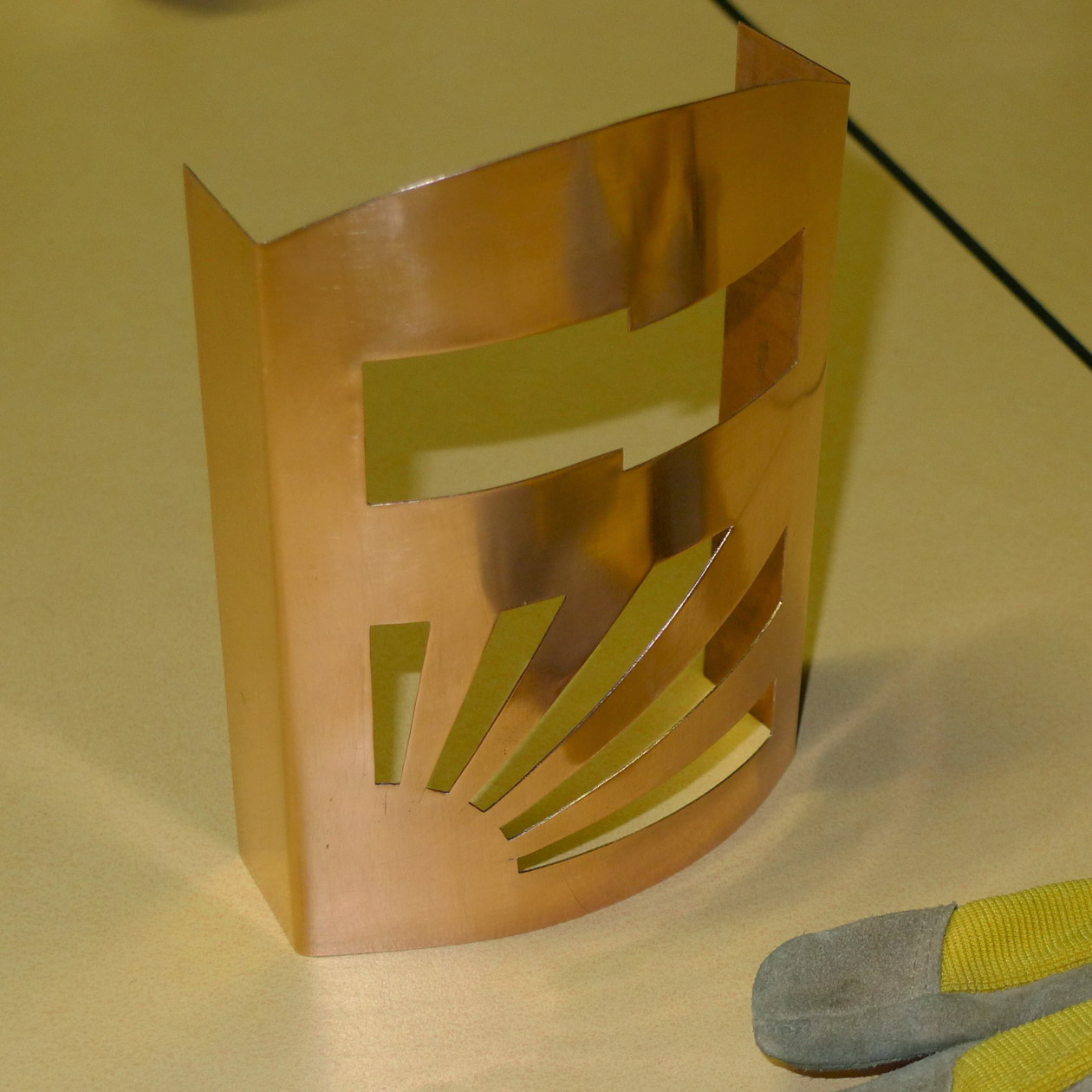
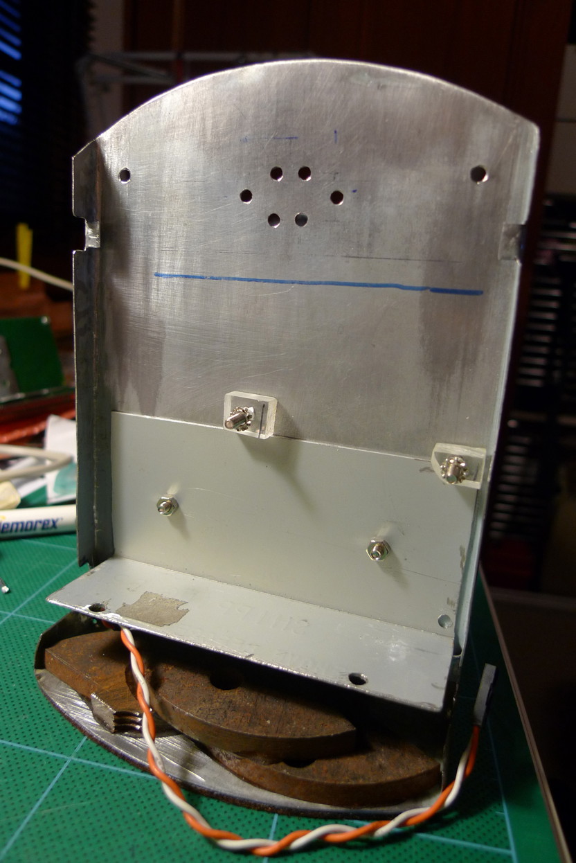
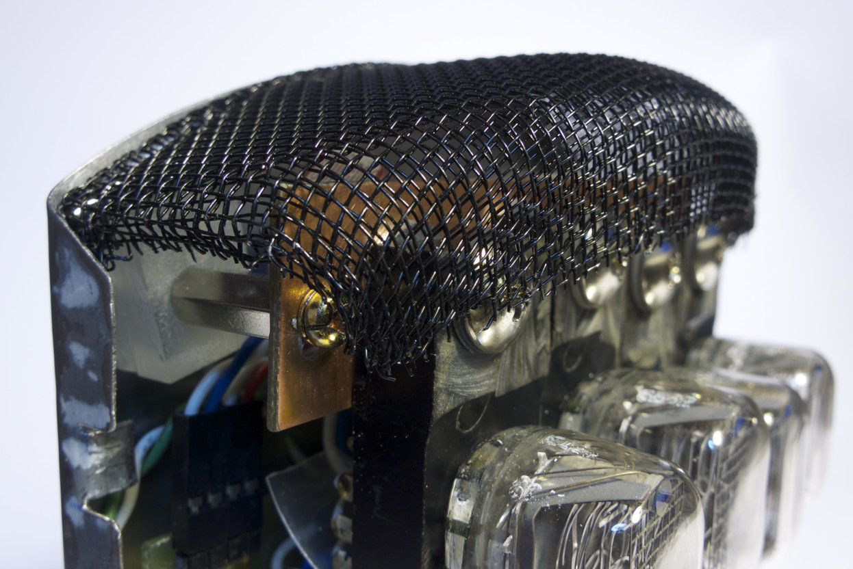
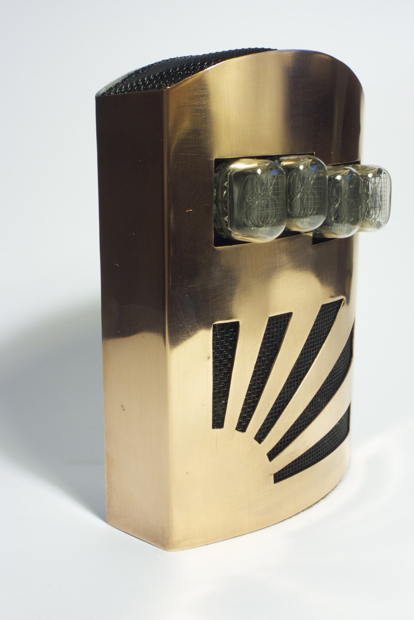
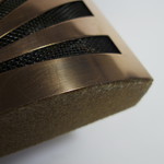
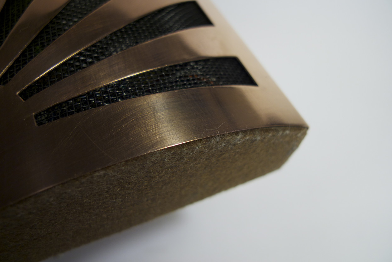
The case front is sheet copper, from the scrap merchant. I assume it was stolen from the roof of an orphanage or church. It’s tinsnipped into shape, polished and folded by hand clamped against angle iron. The curve was applied by hand also, leaving it a little uneven… but hey, this is hand-made not machine-made. The rear half of the case is recycled from the case of an old microwave oven, sawn, folded and soldered to keep the right angle. Some old scrap iron is glued into the base to provide extra stability and the base finished with some non-scratch felt. For the buttons, microswitches are pushed by filed-down nylon machine screwheads. Finally, the front is secured to the back using some very strong magnets. The cutouts are finished with black metal flyscreen mesh.
It looks great in my kitchen. >:)
Constructed June 2007 to November 2011
Images
-
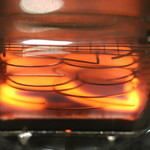
- Look at the magic glow!

-
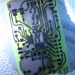
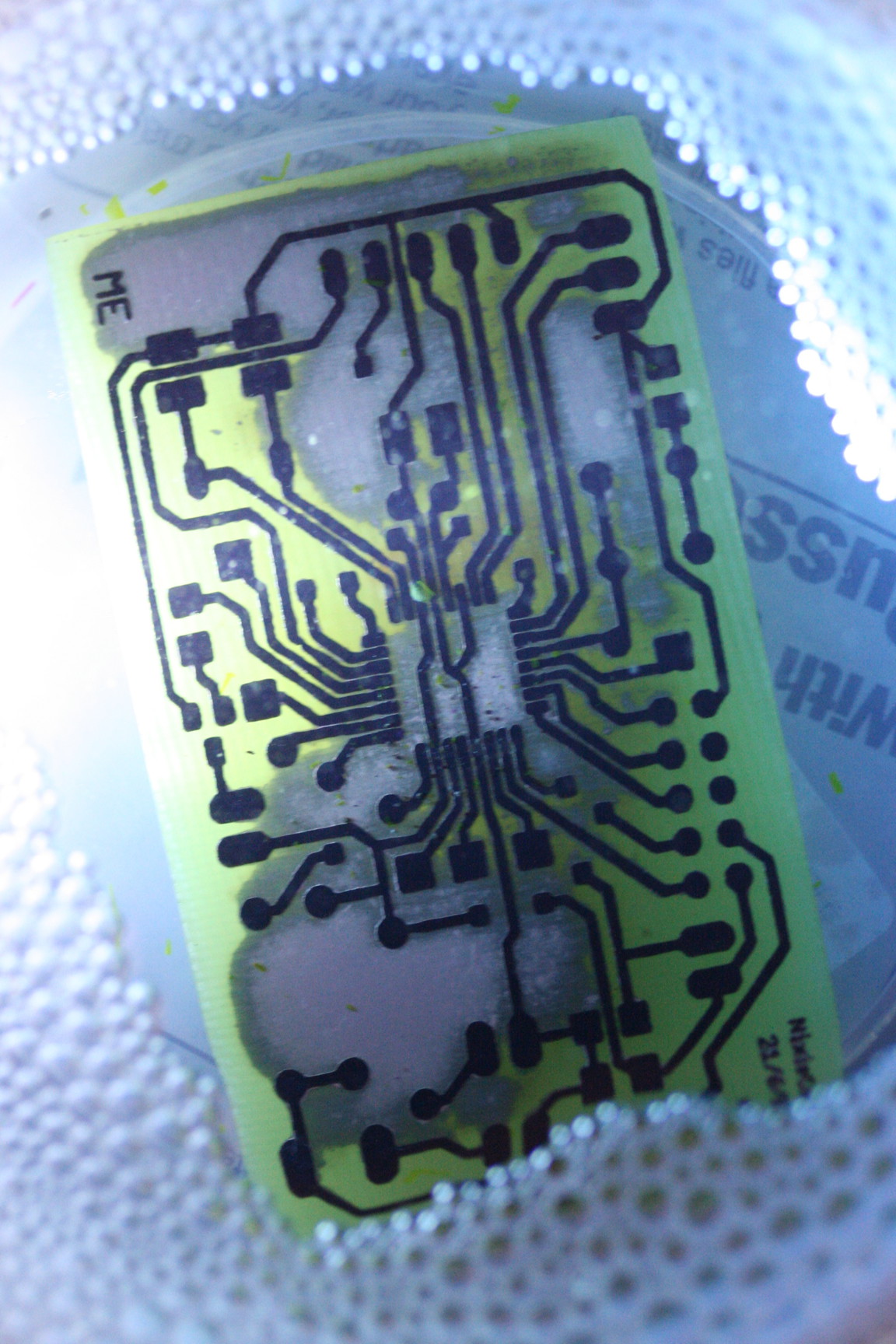
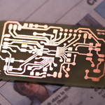
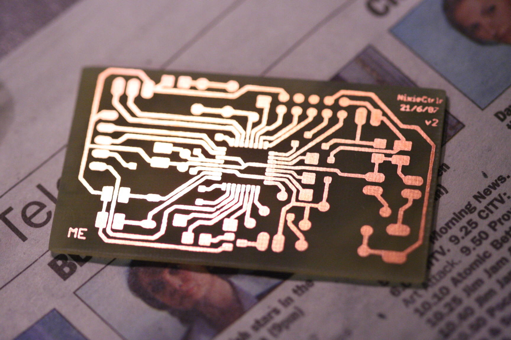
- Kitchen PCB etching
-
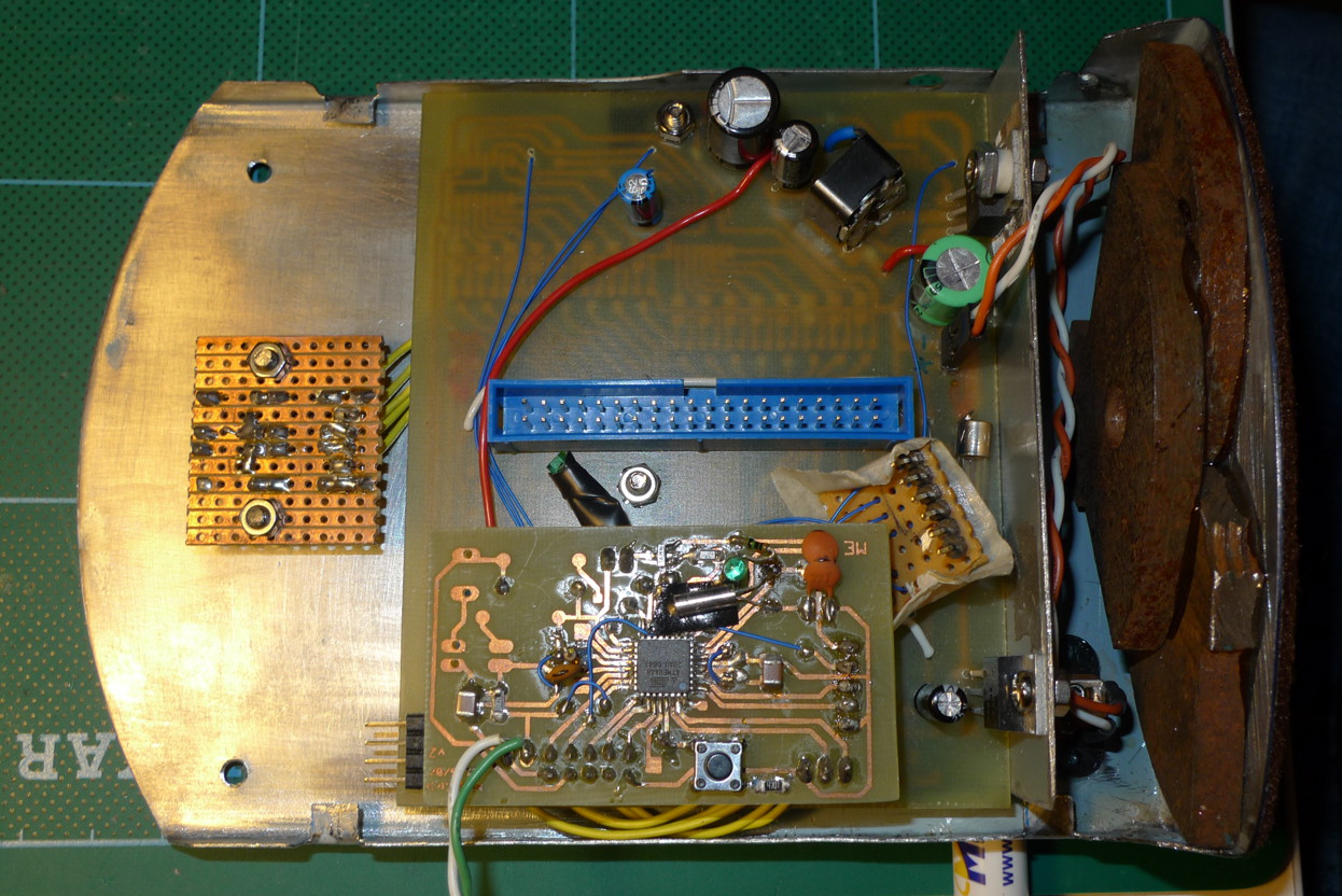
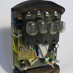
- Control board w/ AVR
-
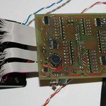
- Driver board w/ PSU, segment drive
-
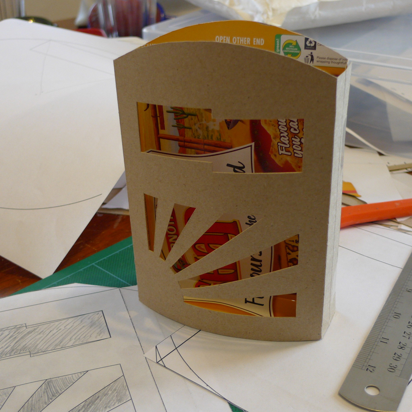
- Case mockup (Pizza Shapes ™)
-
- Case cut & polished
-
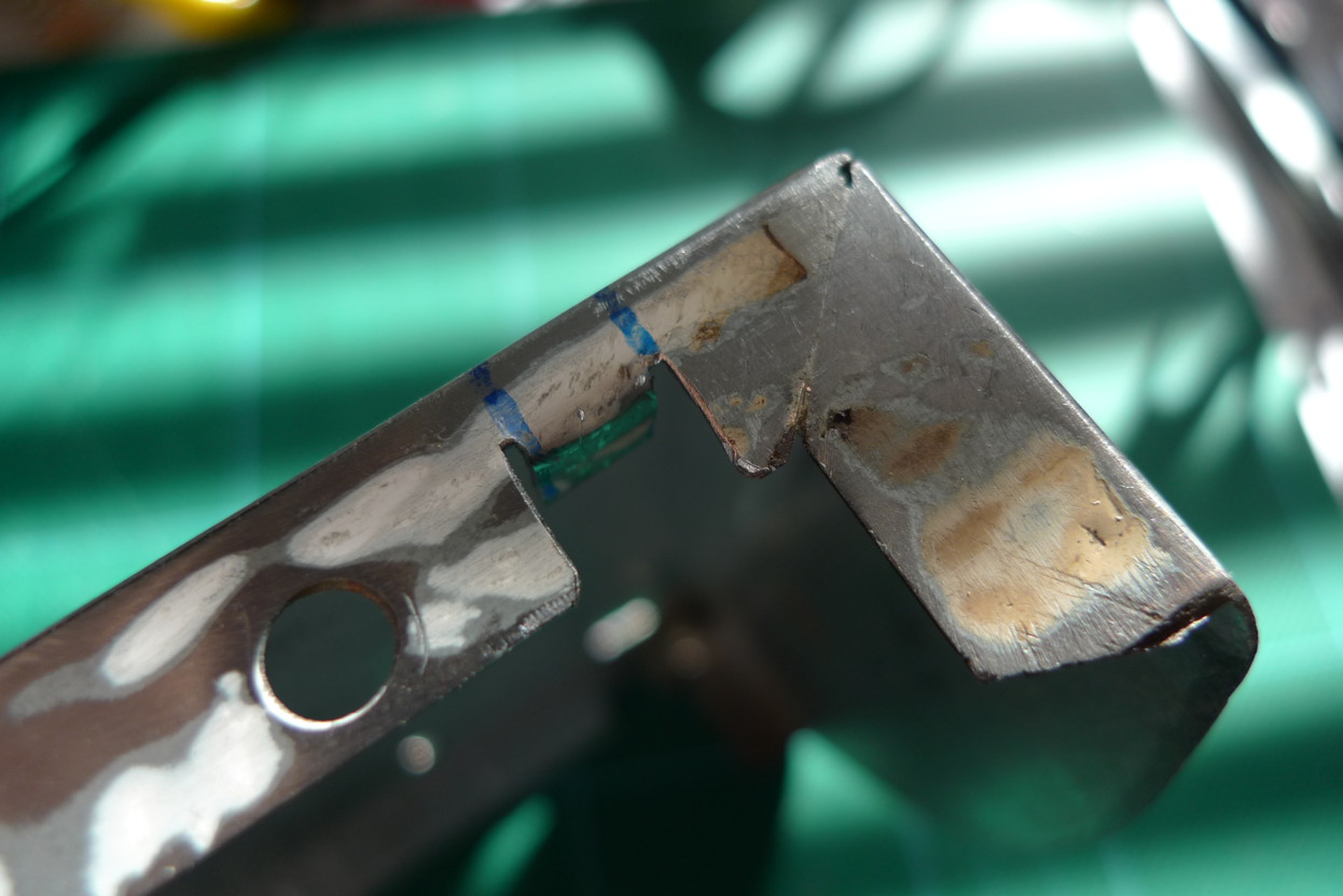
- Case folded

-
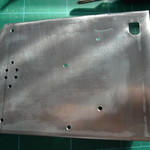
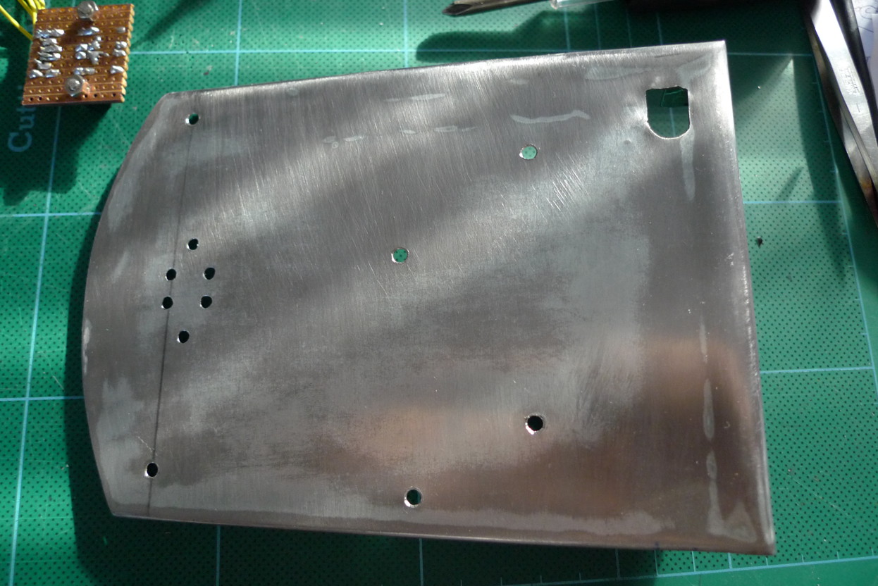
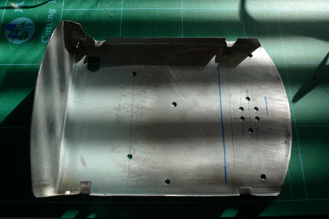
- Rear panel
-
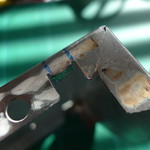
- Soldered fold/join
-
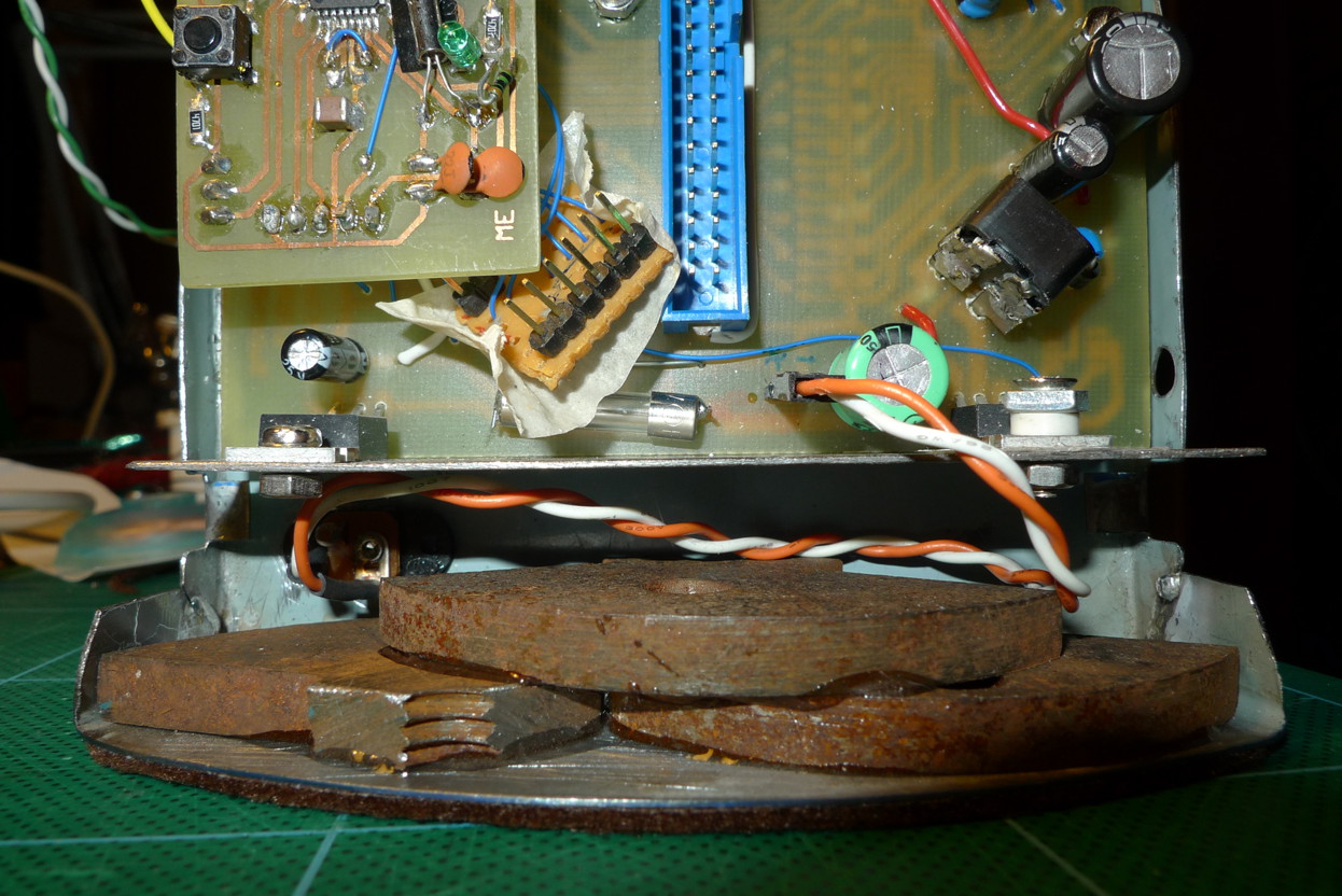
- Initial fitting, scrap iron weights
-
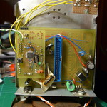
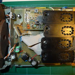
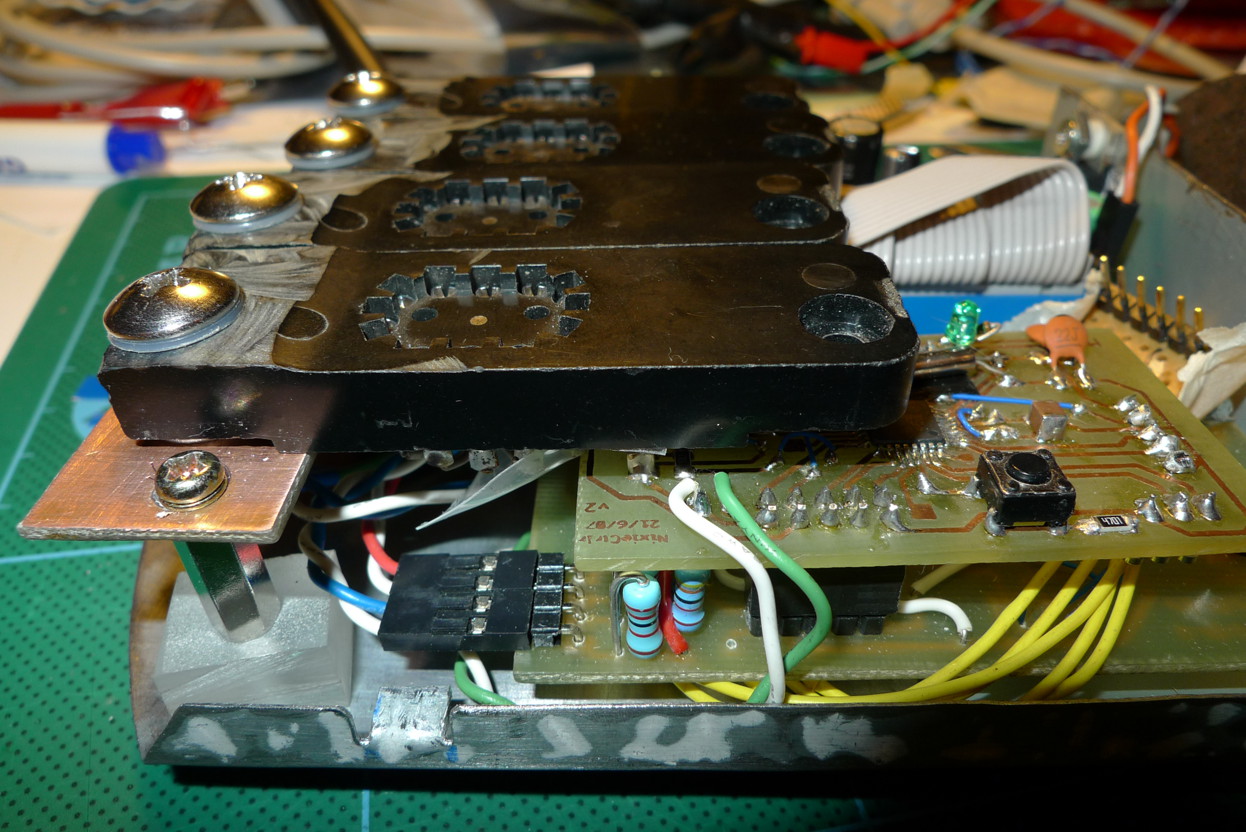
- Messy boards in...

-
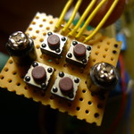
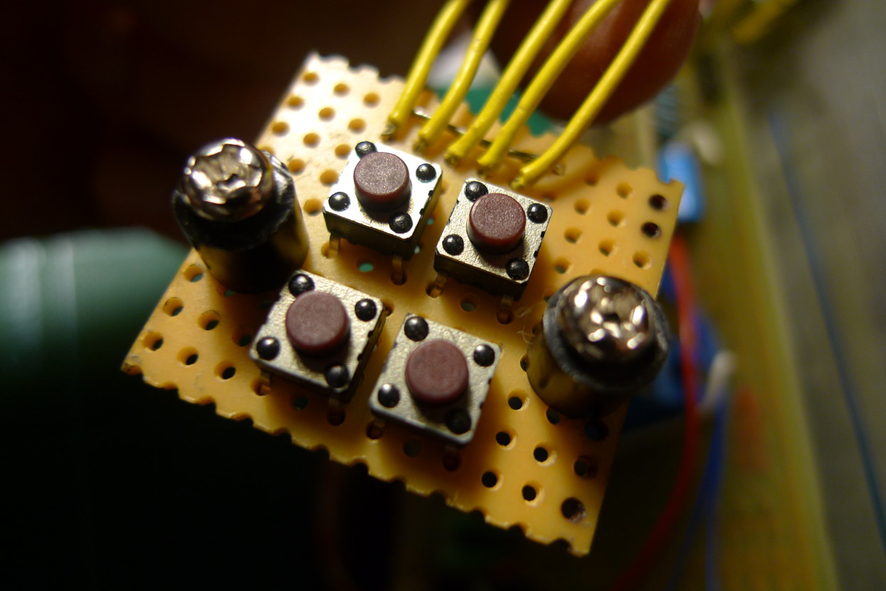
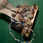
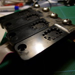
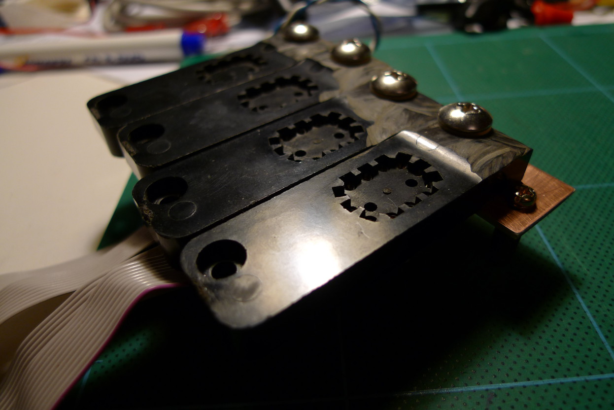
- Control switches
-
- Switches + nylon screws for buttons

-
- Boards in
-
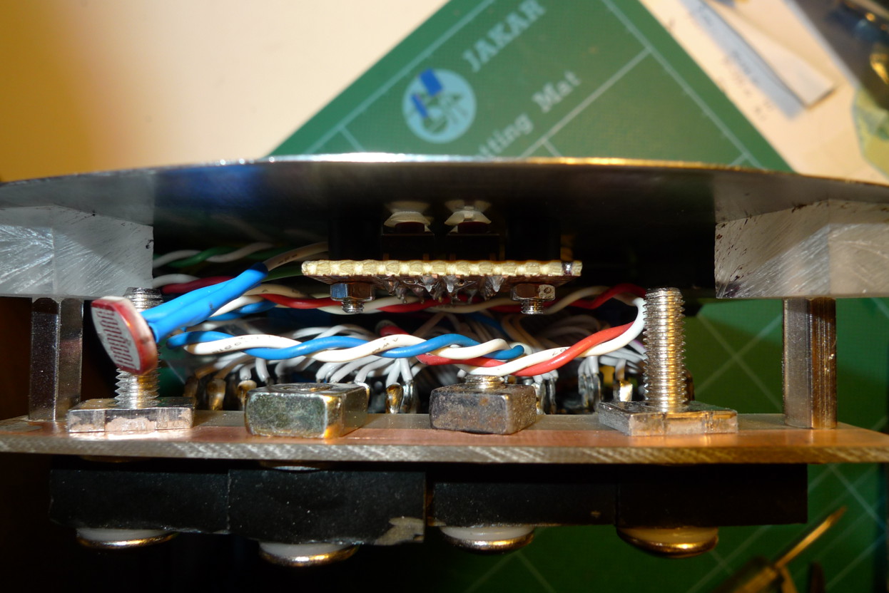
- Tube sockets, FR4 as building material

-
- Tube sockets 2
-
- Tube sockets mounted
-
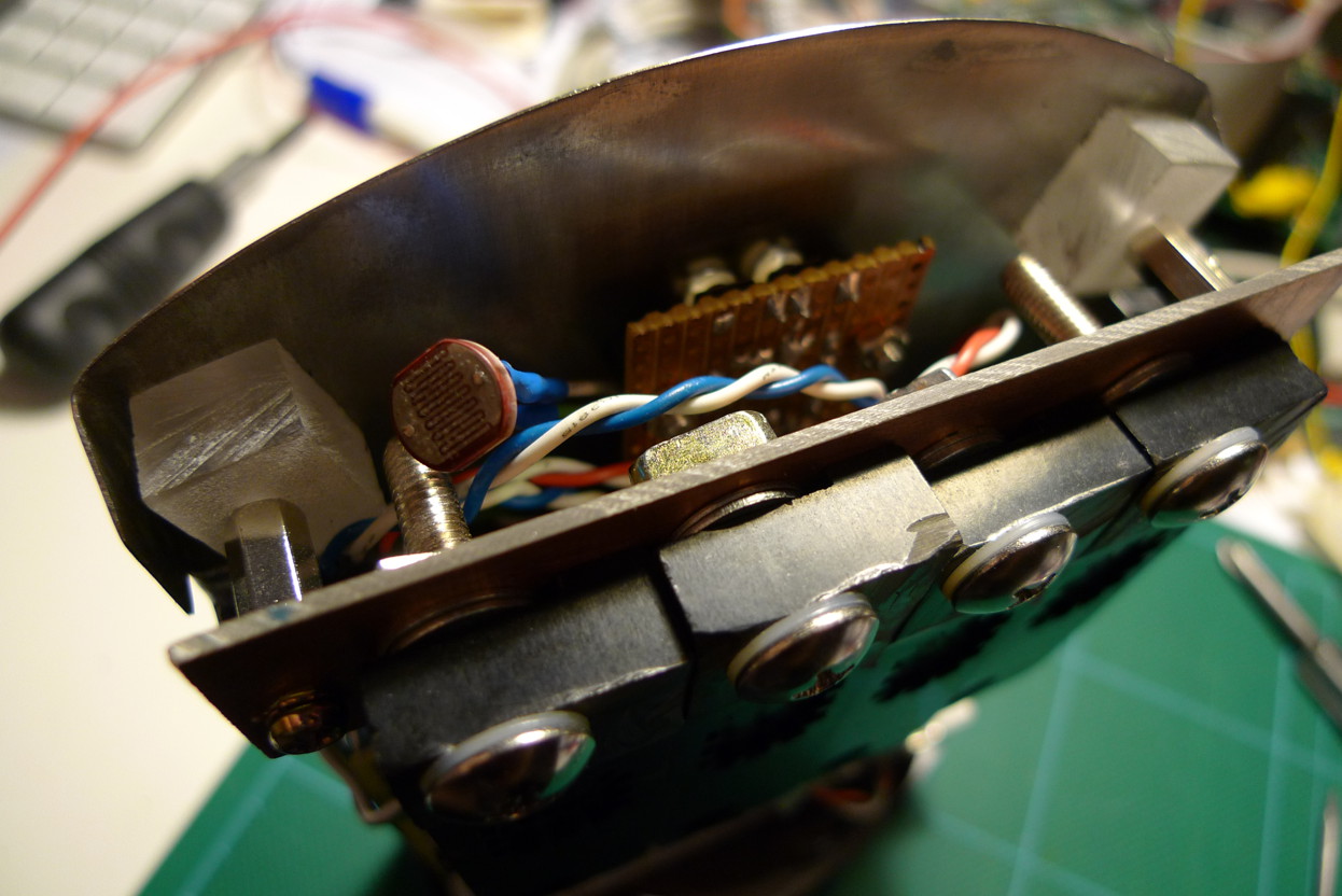
- LDR at top
-
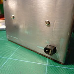
- DC jack

-
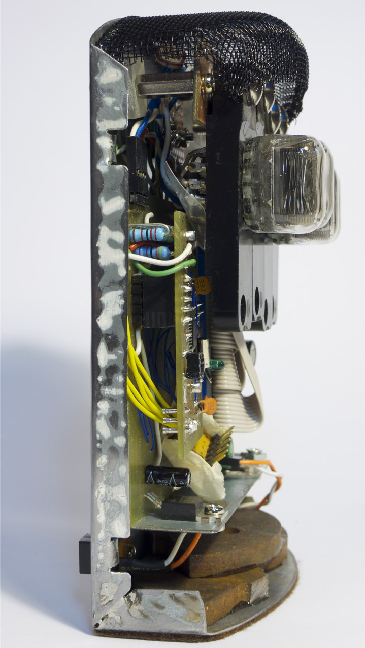
- Finished, cover off

-
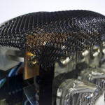
- Metal mesh at top
-
- Done!
-
- Felt foot
-
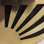
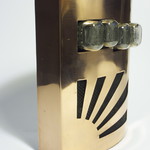
- Closeup of front design

-
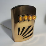
- Powered up


-
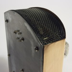
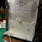
- Top, with buttons