Internet of kitchen lighting, with OSC
This project was completed in June 2015. Wow, is it 2017 already?
In this post, I’d like to say that I wrote a useful little bit of software and built up a crappy hack to demonstrate it but, secretly, the crappy hack came first and I’ve retroactively found something vaguely useful in it. Let’s go:
Let there be lights
We moved house and needed some temporary* under-cupboard lighting for our transitional* 1970s kitchen. Why buy purpose-designed, expensive and great-looking strip lighting when I can instead hack them together myself using hot glue and scrap wire?
Then, I can value-add by using an ESP8266 module to make the lights remote-controllable!
I chose Open Sound Control (OSC) for this, which is traditionally used for media signalling, i.e. ‘a better MIDI, over the network’. I don’t know why I did this instead of using something like Blynk or an HTTP-based control page.
At least I can control my kitchen lights from Ableton Live if the need arises. That need has not arisen so far.
This project is a bit hacky for kitchen lighting, but the OSC+ESP8266 portion might be useful for:
- Controlling real actuators from music sequencers (e.g. solenoids! Boom! Tish!)
- Cheap stage lighting/effects using ESP8266s
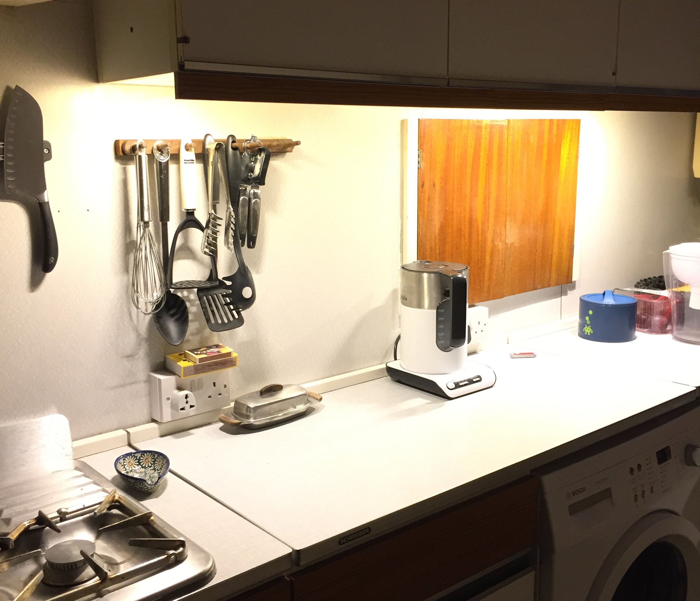
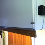
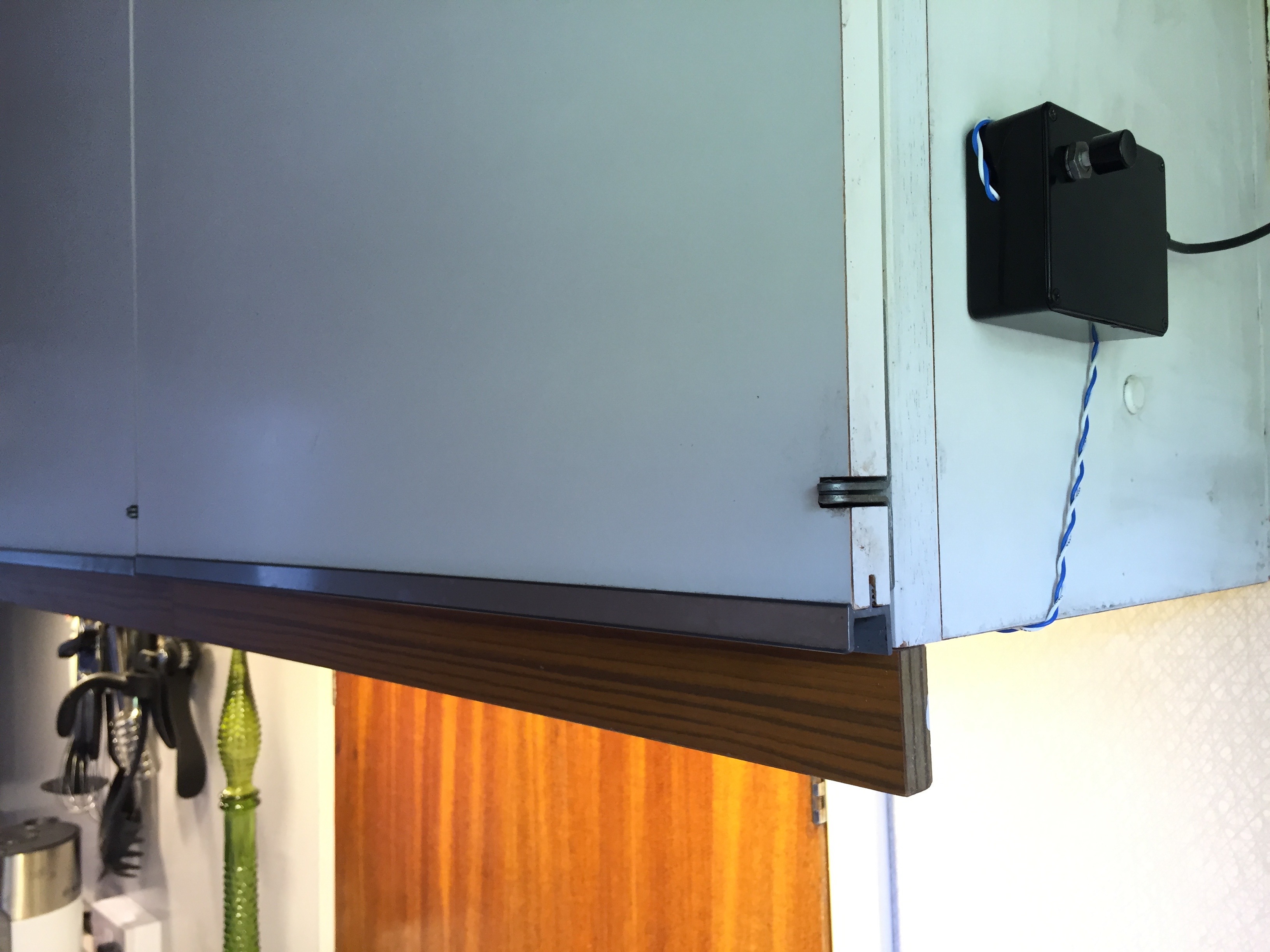
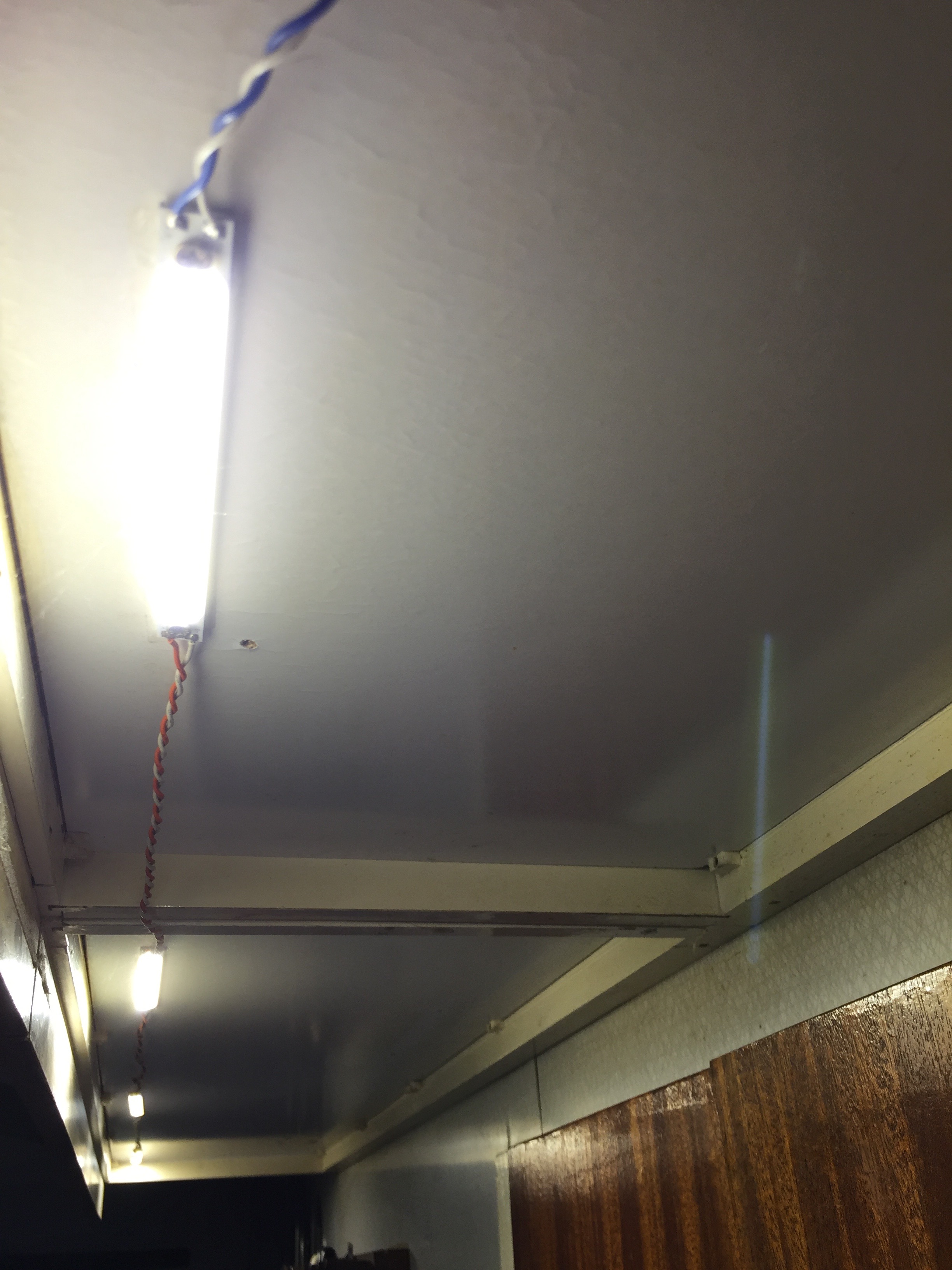
Here’s how the majestic and now well-worn kitchen looks with the new lighting:
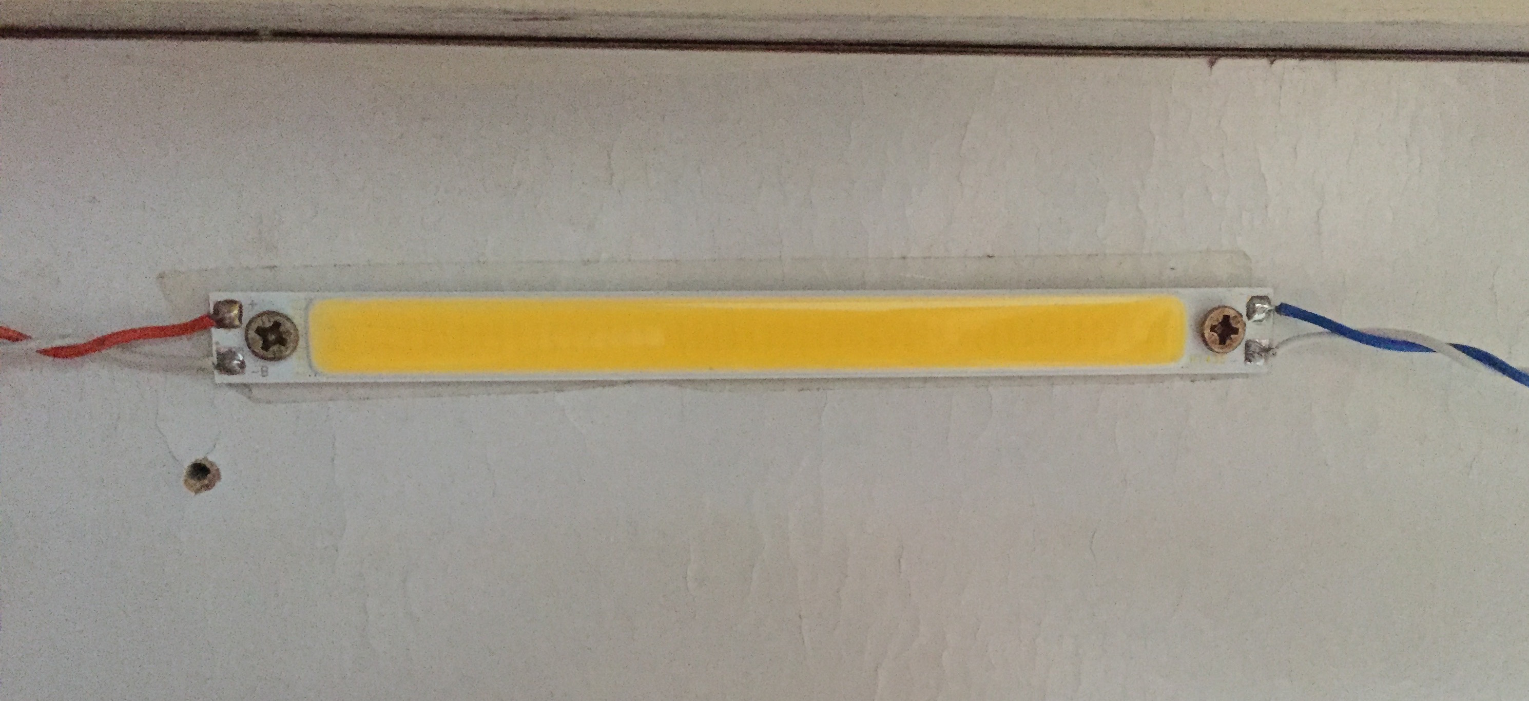
LEDs
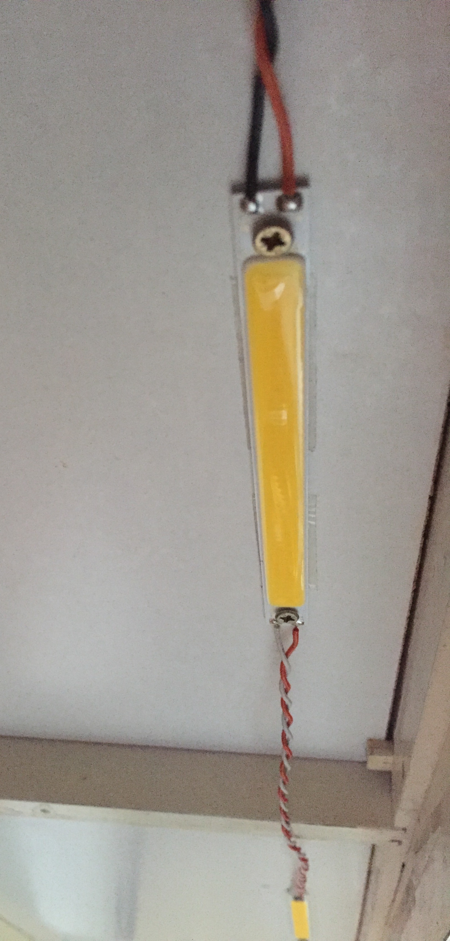
I found some Chip-on-Board (CoB) warm white LED strips on DealExtreme for a couple of quid each. They’re very thin and can therefore be stuck/screwed to the underside of the cupboards without casting light sideways/into the eyes of the person using sharp kitchen implements. I spread out four of them to provide a wide corridor of light. They’re spaced about 50cm apart and the illumination is pretty sharp and even.
They’re quoted to be 315 lumens at 3W, which is almost certainly lies except for the ‘3W’ part, but with four they’re plenty bright.
The four LED strips are daisychained from the controller box, connected in parallel.
Detour: LEDs in parallel
Generally, connecting LEDs in parallel is Not As Good As It Sounds. An LED must be current-limited and when several are put in parallel there is the opportunity for one in the chain to draw slightly more than 1/N of the total supply – LEDs aren’t all identical. Now if that LED is close to the limit anyway, thermal runaway can occur: the LED heats up as it draws more current, causing Vf to drop and therefore more current to flow, causing it to heat up further, then BANG. Now, there’s N-1 LEDs and the total current to the remaining set is that bit higher and the process can continue.
Each CoB LED strip is running about 10V at about 0.3A. The forward voltage of a white LED is usually over 3V, so I believe these strips are parallel sets of 3 LEDs in series. As there’s no series resistor here, how does this work? Well, where LEDs are used in parallel configurations they are carefully characterised and matched to make sure no imbalance occurs in the parallel circuit.
I estimate about 30 die per strip (so ~10 series chains in parallel) and I’m connecting four strips in parallel so there are at least 40 chains that need to be “perfectly matched”.
Given that these strips were £2 from DealExtreme, I’m not confident the LED die have been carefully characterised and matched within a strip let alone across multiple strips. They’re also very bright, so I have a fair leeway to under-drive them and stay cool.
The benefit of waiting 18 months to do a project writeup is I can comment that they remain perfectly reliable over time. :-)
The LEDs are driven from a 12V power brick (rated for 50W), using a constant-current buck converter to step down the 12V but maintain the chosen current. The converter board has a convenient input for on/off/PWM control of the output.
Hardware
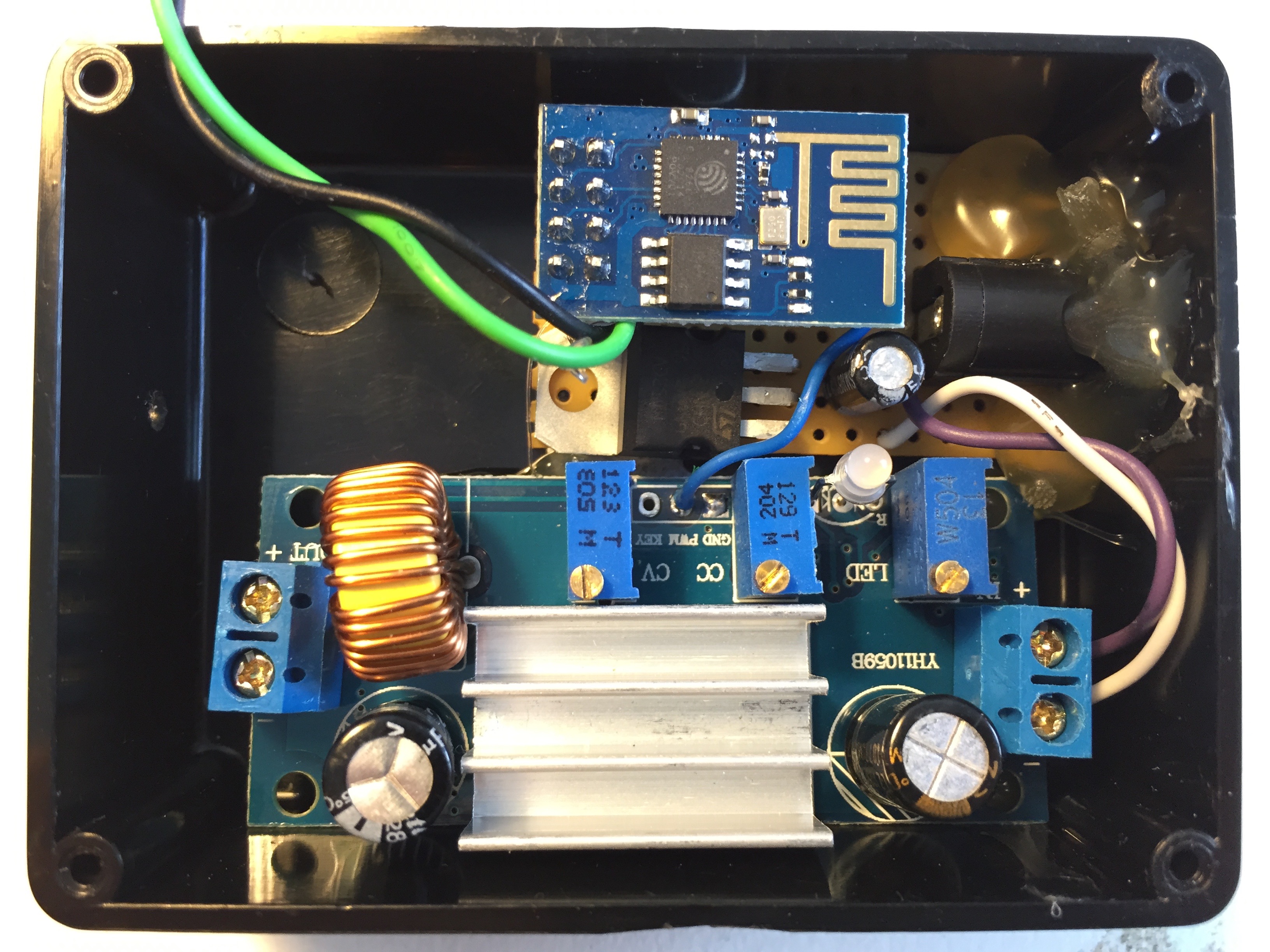
Assembled in a nice little box, the controller hardware consists of the CC power board, an ESP8266, hot glue (I wasn’t joking about that part), a cap and a 3.3V regulator:
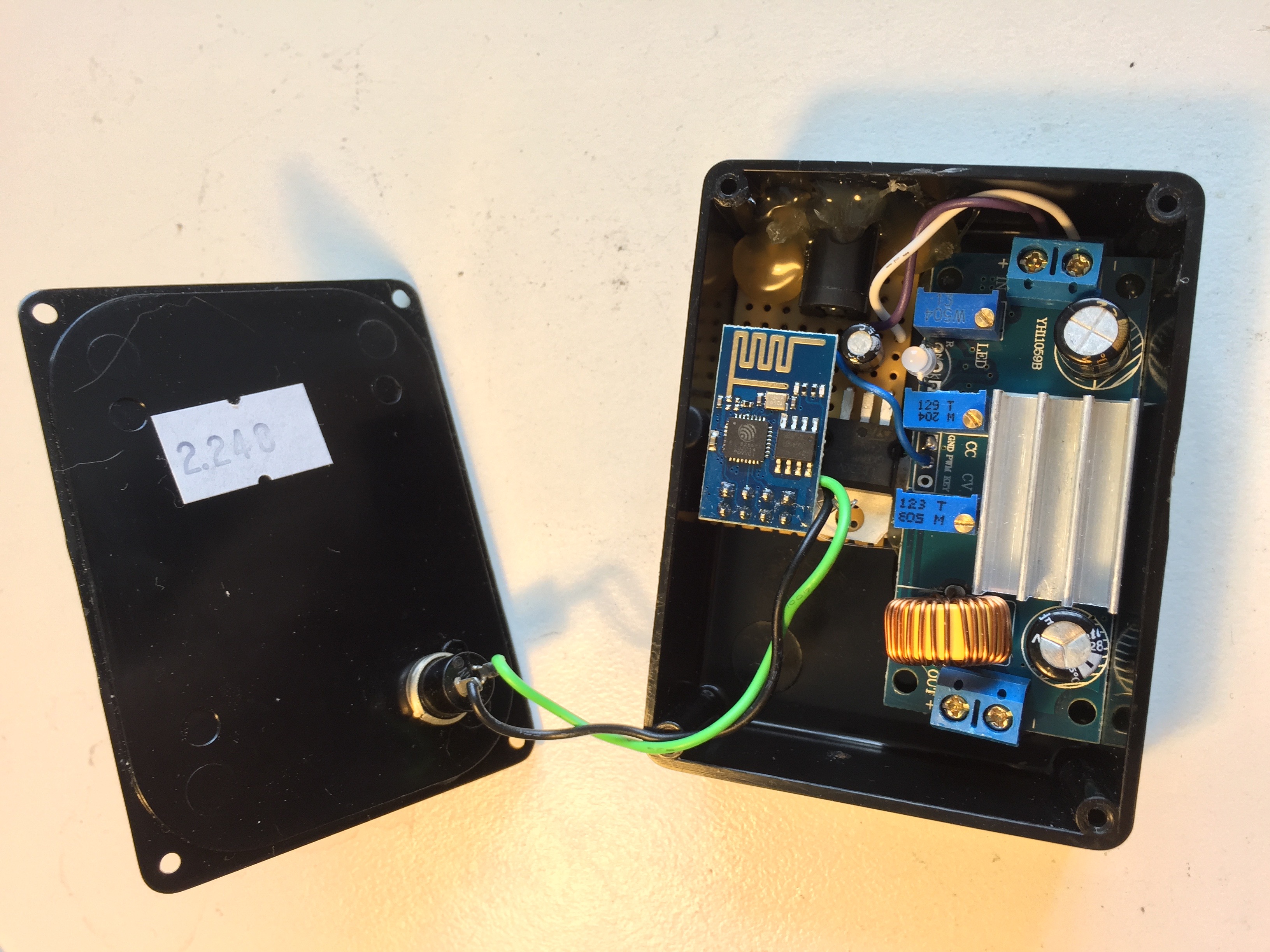
Yes, that heatsink is virtually useless inside a sealed box. Well, it spreads the heat a little. The board doesn’t really get warm enough to worry though.
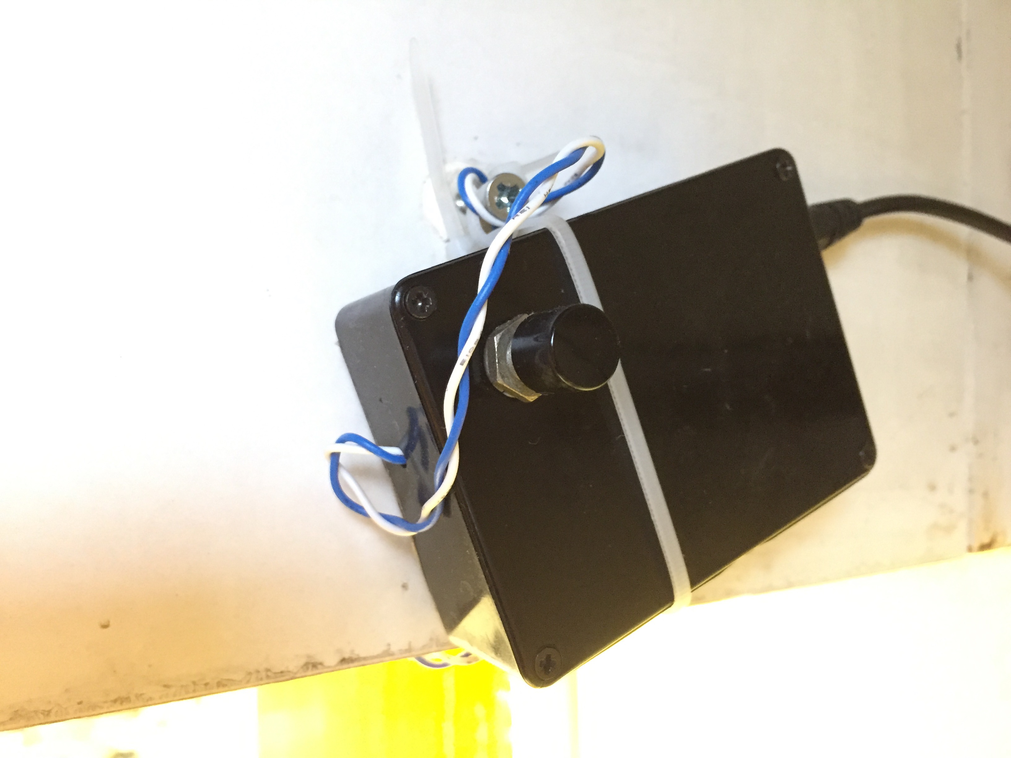
There’s a momentary button on the outside for the old-fashioned way of switching lights on and off, i.e. by pressing a button on the thing you wish to control.
Software
You’ll be amazed that writing the software took a lot longer than building the hardware (given the apparent quality of both…).
The ESP8266 firmware is available via my (now-resurrected) Github:
It builds against the excellent Sming framework. I recommend Sming, it’s nicer than Arduino and has a bunch of useful drivers and a good Out-of-box experience.
The OSC parser is hooked up to a callback function:
osc_reg_handler("/crossfader", cb_cf);
Then, cb_cf is called when an OSC message is sent to that address, with float/int arguments unpacked.
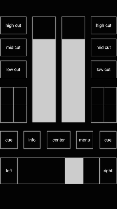
I’m using an iOS app called Control, which is pretty cool. It outputs OSC messages from user-definable UI layouts. The ‘crossfader’ address is emitted by the default ‘DJ’ layout, which has a draggable bar and buttons which control the lights. This saves defining my own UI.
The OSC parser is pretty easy to use and hopefully will be useful for very basic on/off/value-type messages. Aside from a couple of debug statements, it isn’t tied to Sming, or ESP8266.
Closing remarkz
Yes, the cabinets need a paint. Or to be different, new cabinets.
Oh, and about security. Unfortunately, my kitchen countertop lights aren’t cloud-controlled and don’t even have a route to the internet. But that’s OK, as I can pretend we’re switching the lights on and off when we’re away from home and it’s all the same because we’re not there anyway.
See also:
Images
-
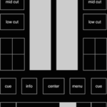
- 'Control' UI
-
- Control box on/off button
-
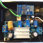
- Closeup inside control box
-
- Bogan wiring
-
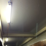
- Bright!
-
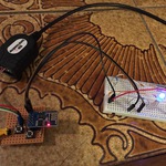
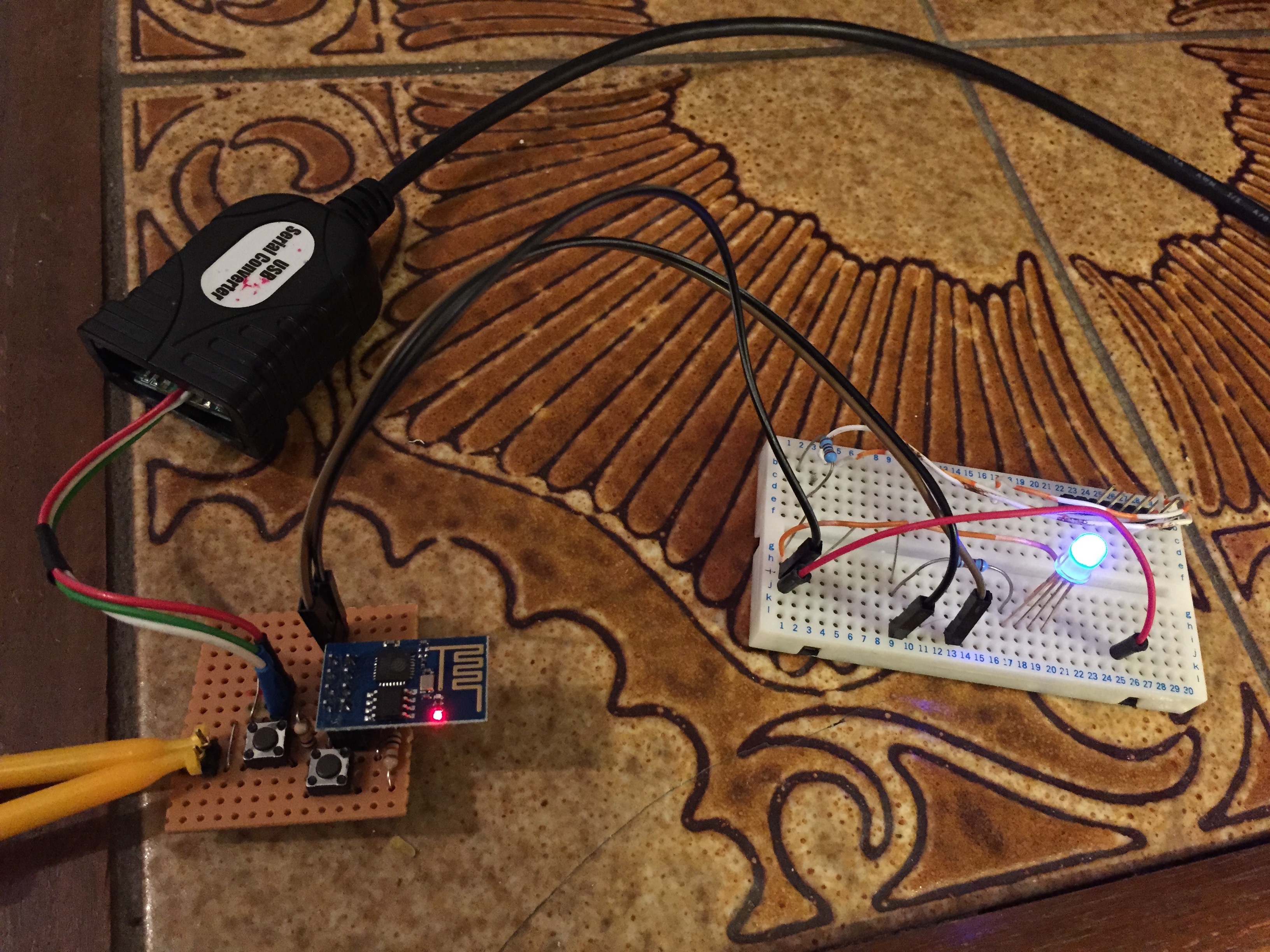
- Prototype with a smaller LED & serial